From Bates DV, Boucot NG, Dormer AE. The pulmonary diffusing capacity in normal subjects. J Physiol 1955; 129: 237-252
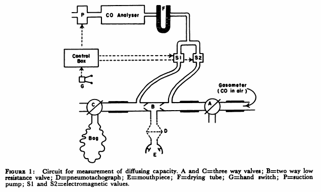
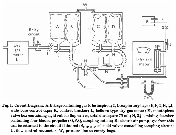
“The mouthpiece (M) contains eight rubber flap valves, four on the inspiratory and four on the expiratory side. Its dead space, including the flexible attachment to the mouth, was 75 ml Beyond the expiratory valves, a mixing chamber (n) of 3-1/2 L capacity contains an induction motor drive four propeller blades. Switching of the sampling circuits is done by solenoid valves (S) in appropriate places in the circuit. Gas analysis was by infrared analyzer of the type described previously (Lawther & Bates, 1953). This was calibrated on two scales, 0-0.15% CO and 0-0.05% CO. The accuracy of this type of instrument is about 3% of scale reading. Gas was drawn through this by a small electric air pump (R), at a rate of 2 l/miin, measured by a rotameter (U). Sampling could be instantly stopped by closing solenoid S1, which was energized through a relay circuit connected to a contact breaker (K), so that, if required, gas was sampled from just beyond the expiratory valve only during inspiration. All exercise was performed on a motor-driven treadmill, the gradient of which was adjustable. When ‘flat’ it actually sloped at a grade of 1:50. At ‘1/2’ slope the grade was 1:10.7. All tubing in the direct breathing parts of the circuit was 5.1 cm in internal diameter and the three-way taps (E to J) had a minimum diameter internally of 3.5 cm. During studies on maximum exercise with ventilation rates up to 90 l/min, the gas meter was disconnected from the circuit and the minute volume measured from the volume of gas collected in the expiratory bag. The pressure swing at the mouthpiece in these circumstances was from -2.6 to +3.4 cm H2O.
“Two initial ‘calibrating’ experiments were performed. The first set of observations consisted of attaching a hand-operated pump of constant stroke volume to the mouthpiece and checking that the gas displaced from the bag containing inspired gas (A or B) into bag C, corresponded with the volume recorded by the gas meter. This volume was measured by wet drum flowmeter, the gas being expressed by positive pressure on the tank at W. The second set of observations compared the mixed expired CO concentration as measured by continuously sampling gas from P, with that of the simultaneously collected expired gas in bag D. For seventeen such experiments, the bag gas averaged 0.002%CO less than the continuous readings. This is just outside the reading error of the meter, and was presumed to results from incomplete bag emptying before the experiment began. Since, however, this error is less than 2% of the average mixed expired CO, it has been disregarded in subsequent experiments. The experiments were performed at different rates of breathing, and at all times the CO meter gas a steady reading on continuous sampling from P; it can be assumed that the box N ensures complete homogeneity of mixed expired gas during these experiments.
“Before each experiment, the infrared meter was set to zero on dry air and its sensitivity checked against a standard cylinder of 0.04% CO. As described later, a zero correction was made during each experiment for ‘interference’ due to water vapour and expired CO2. The deflexion produced by these factors varies with state of ‘decay’ of the detector of the instrument and must be constantly checked.
“The procedure followed in using this circuit varied slightly in different experiments. In those of which the results are shown in Table 2, the subject sat quietly at rest in a chair for 5 minutes. He was then connected to the circuit, the taps being adjusted so that he breathed room air. With the fan N in operation and solenoids LS1 and S2 open o that the meter is sampling continuously from P, a zero reading (Z) is taken on the CO meter. Solenoid S2 is then closed and solenoid S4 is opened, and the subject is switched into 0.14% CO in air contained in bags A and B. The inspired gas concentration (F1) is read on the meter. S4 is closed and S2 again opened, and the mixed expired CO concentration is noted. This usually becomes steady in 1 min or less, but may vary either due to the fact that an equilibrium state had not been reached or due to variations in ventilation. The next stage in the experiment is delayed until a steady mixed expired concentration is being recorded. The fan N is now turned off, and solenoid S2 is closed and S3 is opened. Solenoid S1 is connected to the relay circuit actuated by K. Tap I is now turned so that the gas meter is connected to the inspired gas tank containing bag A and B. At the same moment tap G is turned o all expired gas is collected in bag C; this gas is analyzed for CO2 and O2 so that the appropriate R.Q. correction can be applied. For the next minute (timed by stopwatch) the gas meter will read the minute volume, and the meter will sample from O during each inspiration only.”