From “Methods in pulmonary physiology”, by Bertels H, Bucherl E, Hertz CW, Rodewald G, Schwab M. Translated by Workman JM. Hafner Publishing Co., 1963, page 39.
From “Methods in pulmonary physiology”, by Bertels H, Bucherl E, Hertz CW, Rodewald G, Schwab M. Translated by Workman JM. Hafner Publishing Co., 1963, page 39.
From “Methods in pulmonary physiology”, by Bertels H, Bucherl E, Hertz CW, Rodewald G, Schwab M. Translated by Workman JM. Hafner Publishing Co., 1963, page 42.
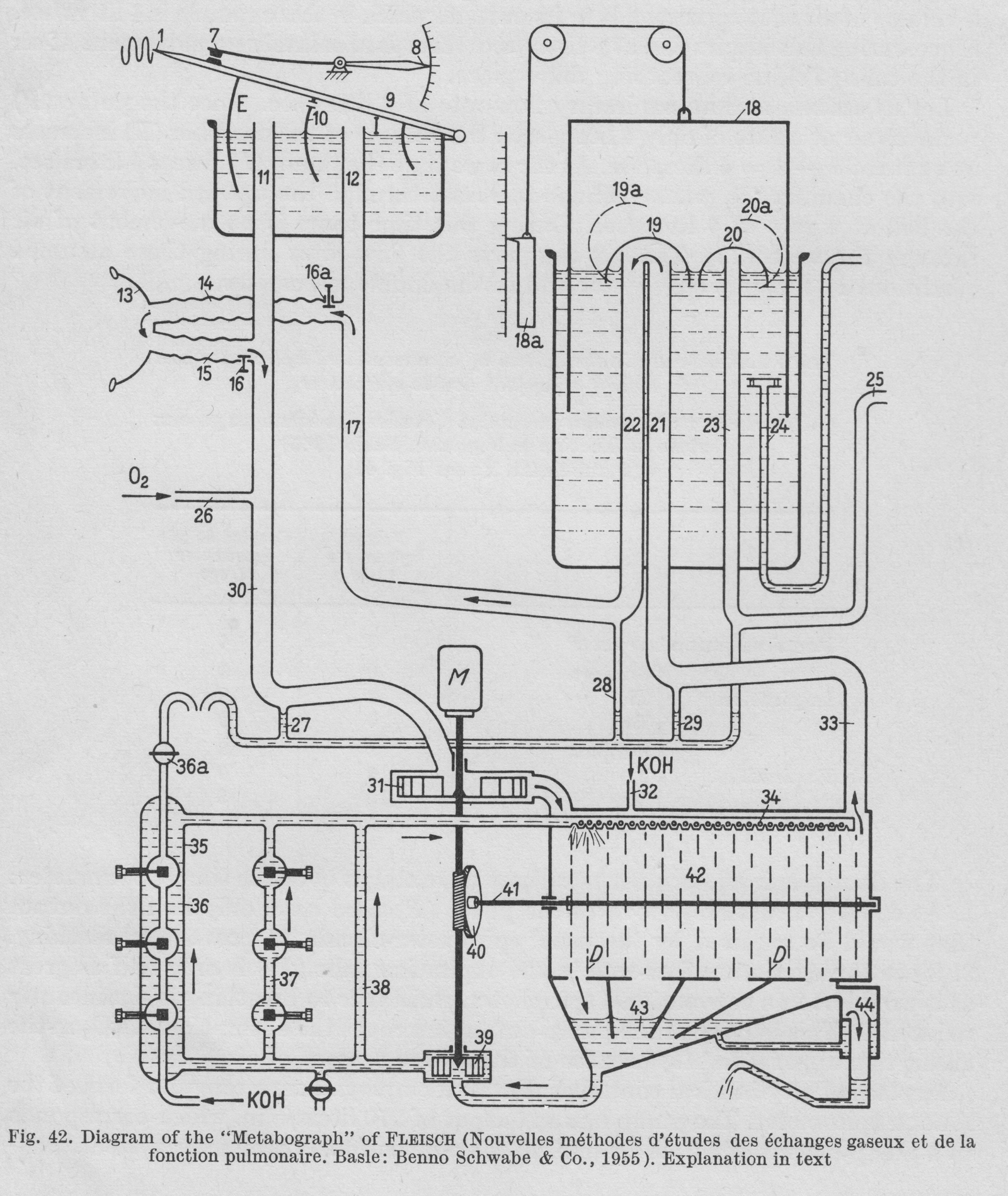
“Figure 42. is a diagrammatic representation of the construction of the apparatus. A motor (M) drives the pump (31), which sends air int the CO2 abdorbant chamber (42). Freed of CO2, the air passes by way of the tube (33) into (21), then under the valve (19). From here it is led through tubes (22), (17), (14), (15), (30) and returns to the pump (31). During inspiration the bell (9) of the double spirometer sinkes and a corresponding volume of air passes out of (I) through tubes (12) and (14) into the lungs, while the pump removes an equal volume from the chamber (E) through tubes (11), (30). During expiration, the volume of air that leaves the lungs travels by way of (15) and (11) to chamber (E), while the corresponding volume passes into chamber (I) through (17) and (12). This the bell (9) rises. The partitioning septum (10) is pierced by a small opening so that some air is always passing from chamber (I) into chamber (E), preventing accumulation of CO2.
“Volume stabilization is achieved through an electrical contact (7). When contact is broken, oxygen is added to the system by a pump through (26). This establishes the bell in the middle position, and maintains the O2 concentration in the system practically constant. When the bell touches the contact (7), the total volume of the system is 32 liters.
“In the absorption chamber (42) there are rotating discs, over which KOH runs. This arrangement provides the larges possible surface area for CO2 absorption. The KOH is collected in a sump (43), removed hence by a pump (39) and sent back to the distribution chamber (34) by three parallel routes (38), (37) and (36). Recording of CO2 production is based on the measurement of the electrical conductivity of the KOH. Throughout the period of study the conductivity of the KOH is held constant. When the degree of alkalinity of the KOH is reduced by the expired CO2 resulting in reduced conductivity, fresh KOH is added through the side tube (32) until the original conductivity is restored. Thus the CO2 production of the subject under study is determined directly by the amount of fresh KOH that has been added.”
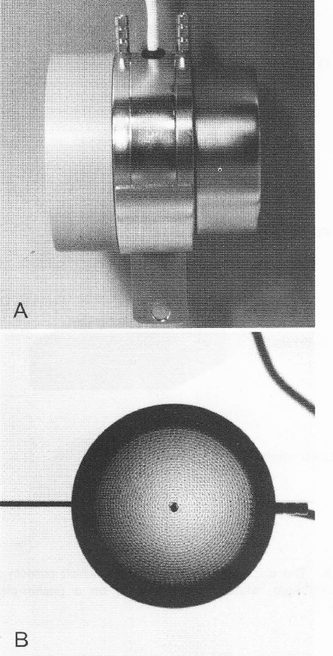
Side and front views of a Fleisch pneumotach. From “Pulmonary Function Testing: A Practical Approach” by Jack Wanger, published by Williams and Wilkins, 1992, page 14.
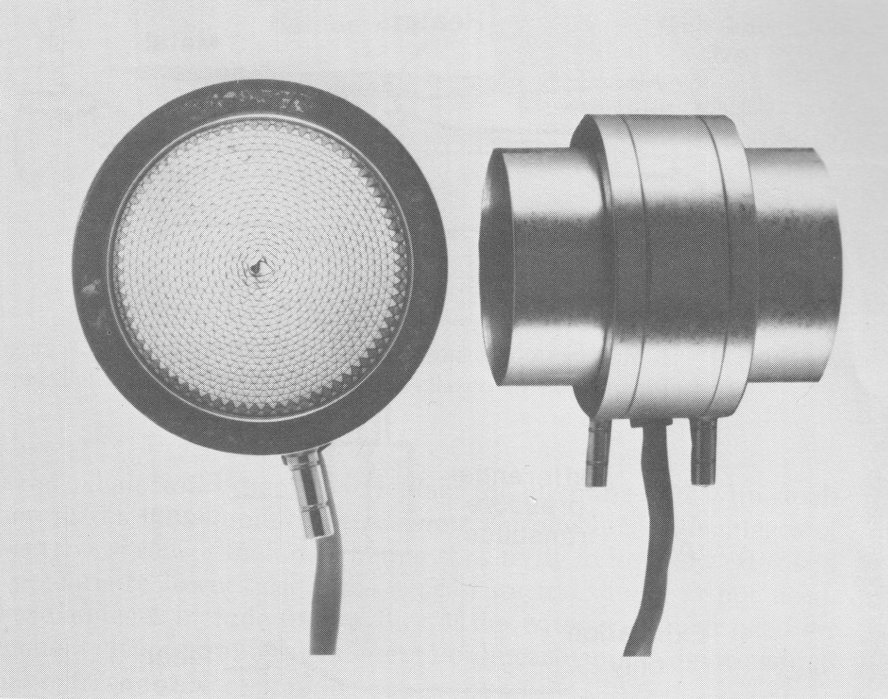
A Fleisch #3 pneumotach. From Office Spirometry. A practical guide to the selection and use of spirometers. By PL Enright and RE Hyatt. Published by Lea and Febiger, 1987. Page 79.
From “New methods of studying gaseous exchange and pulmonary function” by Alfred Fleisch, published by Charles C. Thomas, 1960, page 103.
From “New methods of studying gaseous exchange and pulmonary function” by Alfred Fleisch, published by Charles C. Thomas, 1960, page 81
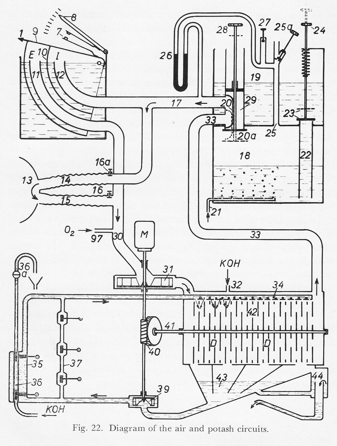
“Figure 22 shows a schematic representation of the air circuit. The motor M operates the rotary blower 31 which drives the air into the chamber 42 where the CO2 is absorbed. After it has been freed of CO2 the air passes through the tube 33, the distributor 20 and the pipe 17. It reaches the mask 13 through the corrugated tube 14 and leaves it through the corrugated tube 15 and the pipe 30, returning to the blower 31. When the subject is not breathing, the air current does not flow through the double-partition spirometer 9-12 which is by passed. The bell 9 of the double spirometer is divided into two parts by the partition 10 and thus forms two chambers I and E for inspiration and expiration respectively. At inspiration the bell 9 is lowered and some of the air from chamber I passes through tubes 12 and 14 to the lungs; blower 31 draws an equal volume from the chamber E through tubes 11 and 30. At expiration the air from the lungs fills the chamber E through the pipes 15 and 11, and the chamber I is filled with air coming from pipe 17 though the pipe 12; the bell 9 therefore rises.
“The partition 10 has a small opening in order that some air can always pass from the chamber I to the chamber E so that the latter can be free from CO2.
“The consumption of oxygen by the subject causes the bell 9 of the spirometer to fall slowly. As soon as the bell no longer closes the contact 7 at expiration, a greater quantity of oxygen is pumped into the system from a container through the junction 97 until the contact 7 is once again established. By means of this automatic regulation the bell 9 tends to remain always at a mean position and the percentage of oxygen tends to remain constant. The quantity of oxygen which enters the system through the junction 97 is discussed in section G.
“After the mask has been fitted to the face of the subject, it often happens that the spirometer bell 9 is not a suitable height to operate the contact 7. By pressing the button of the valve 16, atmospheric is admitted into the circuit so that the bell 9 rises. Conversely, pressure on the button of valve 16a expels so air and the bell falls. When the bell 9 is at the right height to operate contact 7 the total volume of the circuit is 42 liters.”
From “New methods of studying gaseous exchange and pulmonary function” by Alfred Fleisch, published by Charles C. Thomas, 1960, page 51.
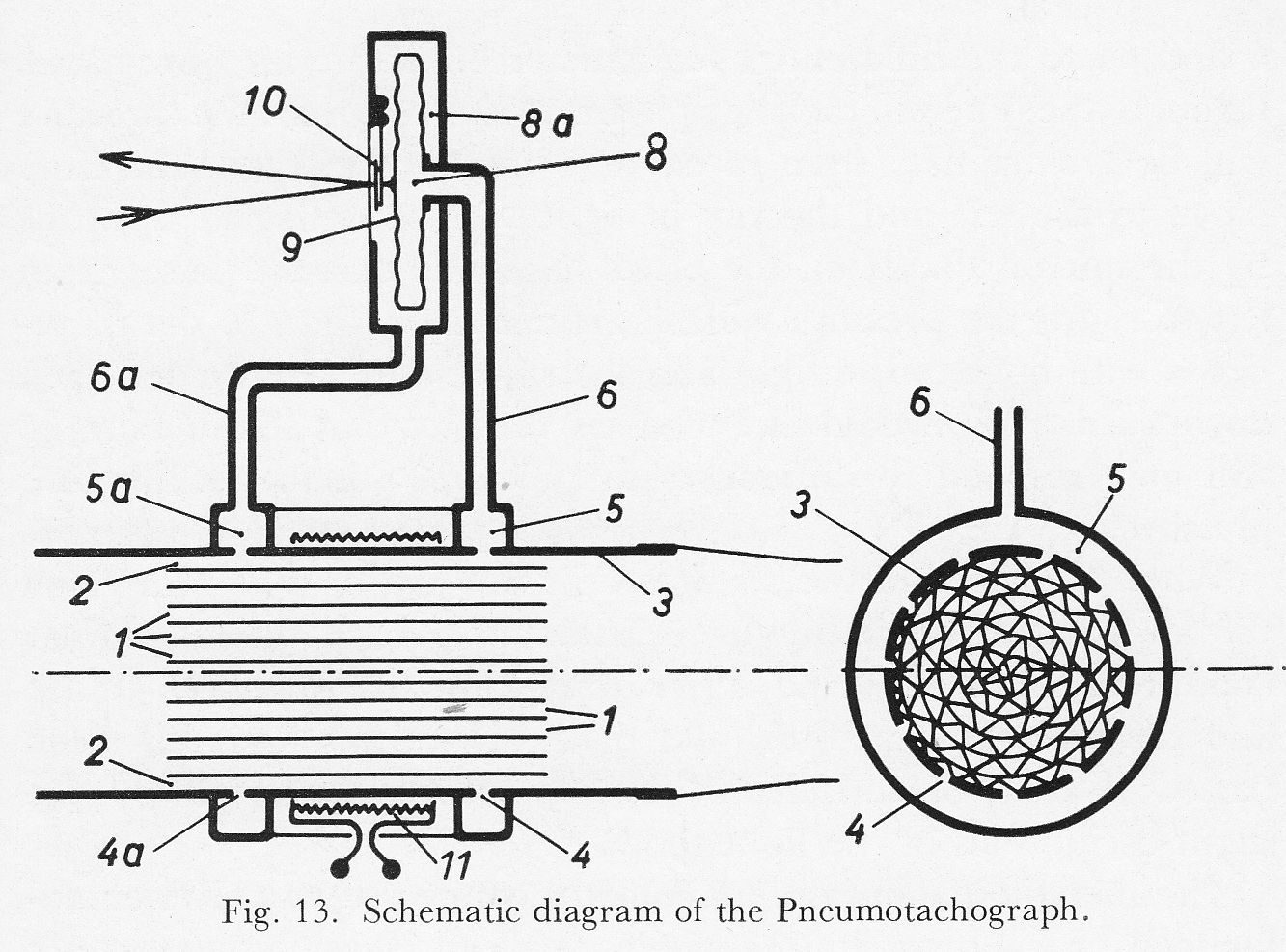
“The great interest currently enjoyed by pneumotachography has induced us to improved our old instrument which separated the air flow into a number of parallel tubes 130 mm long and 1.8 mm interior diameter. The length of the air passages is now reduced to 32 mm, thus greatly decreasing the dead space. To improve the proportionality the inner diameter of the air passages is reduced to 0.8 mm.
“The system of air passages is obtained by rolling together a thin corrugated nickel strip and a flat strip (Fig. 13). The outer corrugated layer 2 is used for the pressure tappings. The brass tube 3 has two rows of small holes 4 and 4a distributed over its whole circumference and communicating with the annular ducts 5 and 5a. The pressure is the transmitted through the tubes 6 and 6a to the differential manometer 8. If the air flow passes through the pneumotachograph from right to left the pressure will be greater in 5 than in 5a; the membrane 9 will therefore move to the left and the ray of light will be deflect upwards by the mirror 10. If on the other hand the current passes fro left to right, the pressure will be greater in 5a than in 5, the membrane will move to the right and the ray of light will be deflected downwards. We would like to stress the fact that the membrane will only respond to differences in pressure, not to the absolute pressure.
“When the speed of the air flow does no exceed a certain value the air particles move in the pneumotachograph under laminar conditions, thus ensuring strict proportionality between speed and the deflection of the ray of light. One this limit has been passed a state of turbulence ensues, easily recognized by the slight oscillation of the light spot.
“The metallic membrane manometer connected to the pneumotachograph has a natural frequency of about 20 cycles per second; since the physiological oscillations of the air flow are slower, a rapid reaction and a reliable recording are assured.”
From “New methods of studying gaseous exchange and pulmonary function” by Alfred Fleisch, published by Charles C. Thomas, 1960, page 51.
From “New methods of studying gaseous exchange and pulmonary function” by Alfred Fleisch, published by Charles C. Thomas, 1960, page 10.
From “New methods of studying gaseous exchange and pulmonary function” by Alfred Fleisch, published by Charles C. Thomas, 1960, page 5.
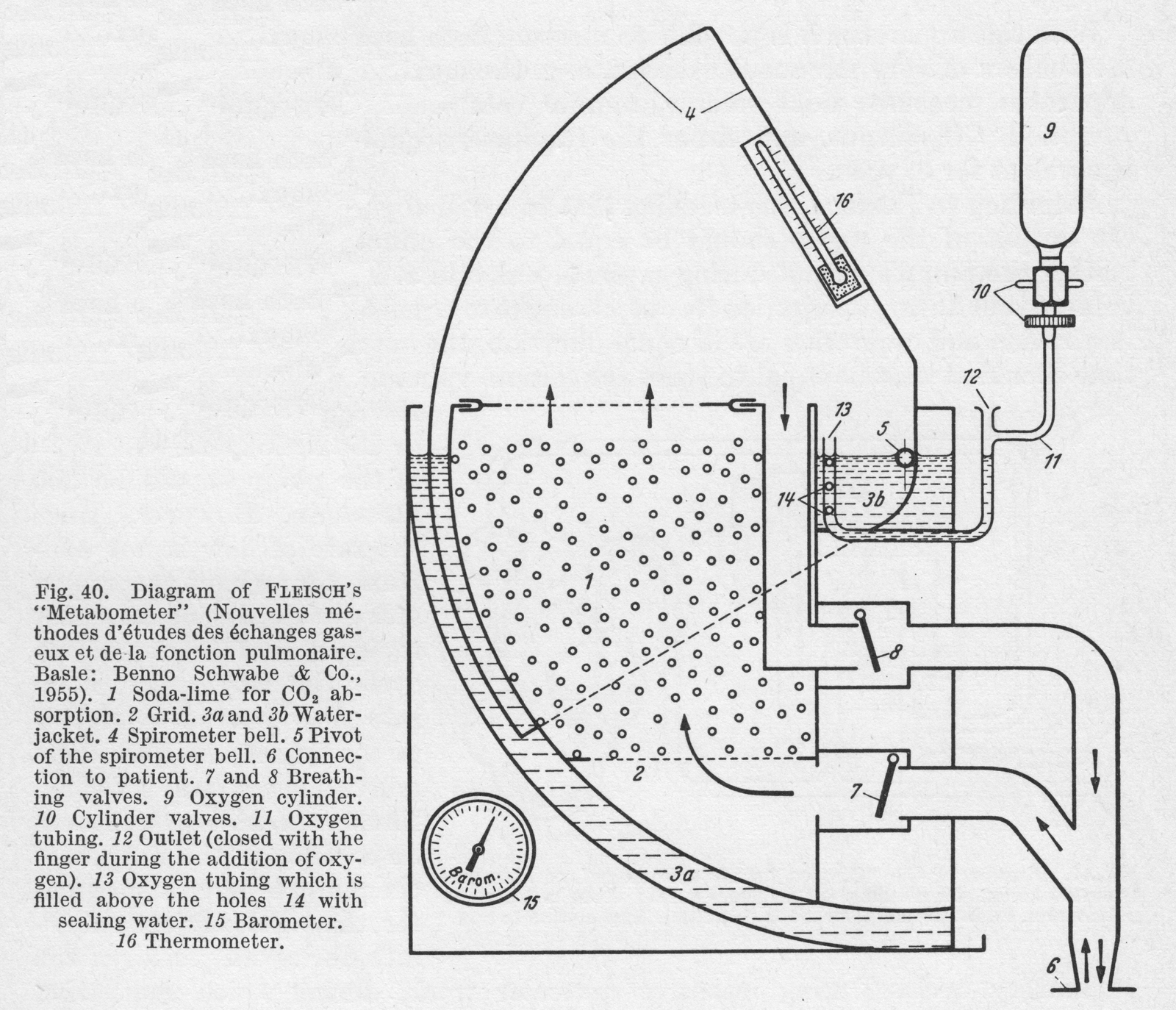
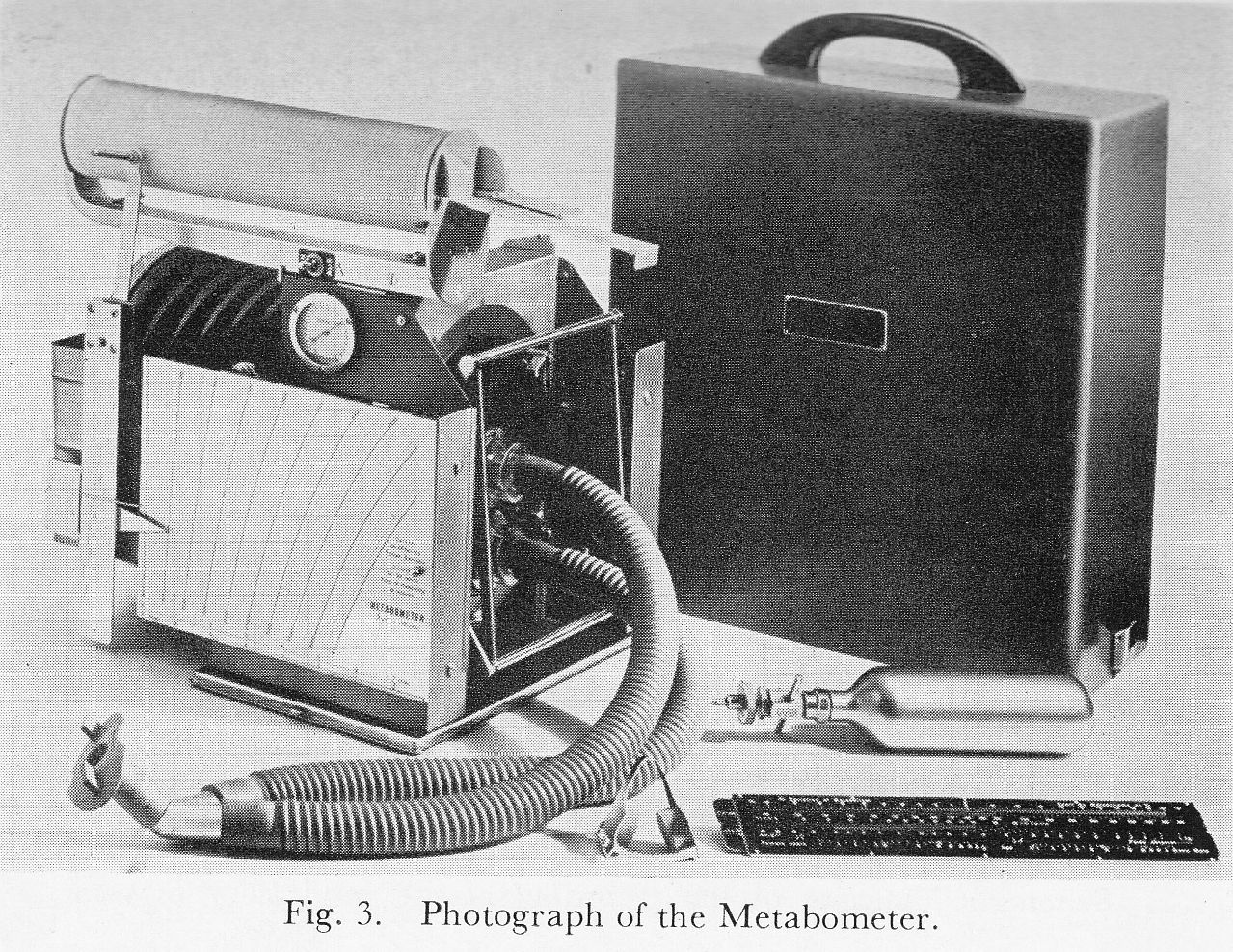
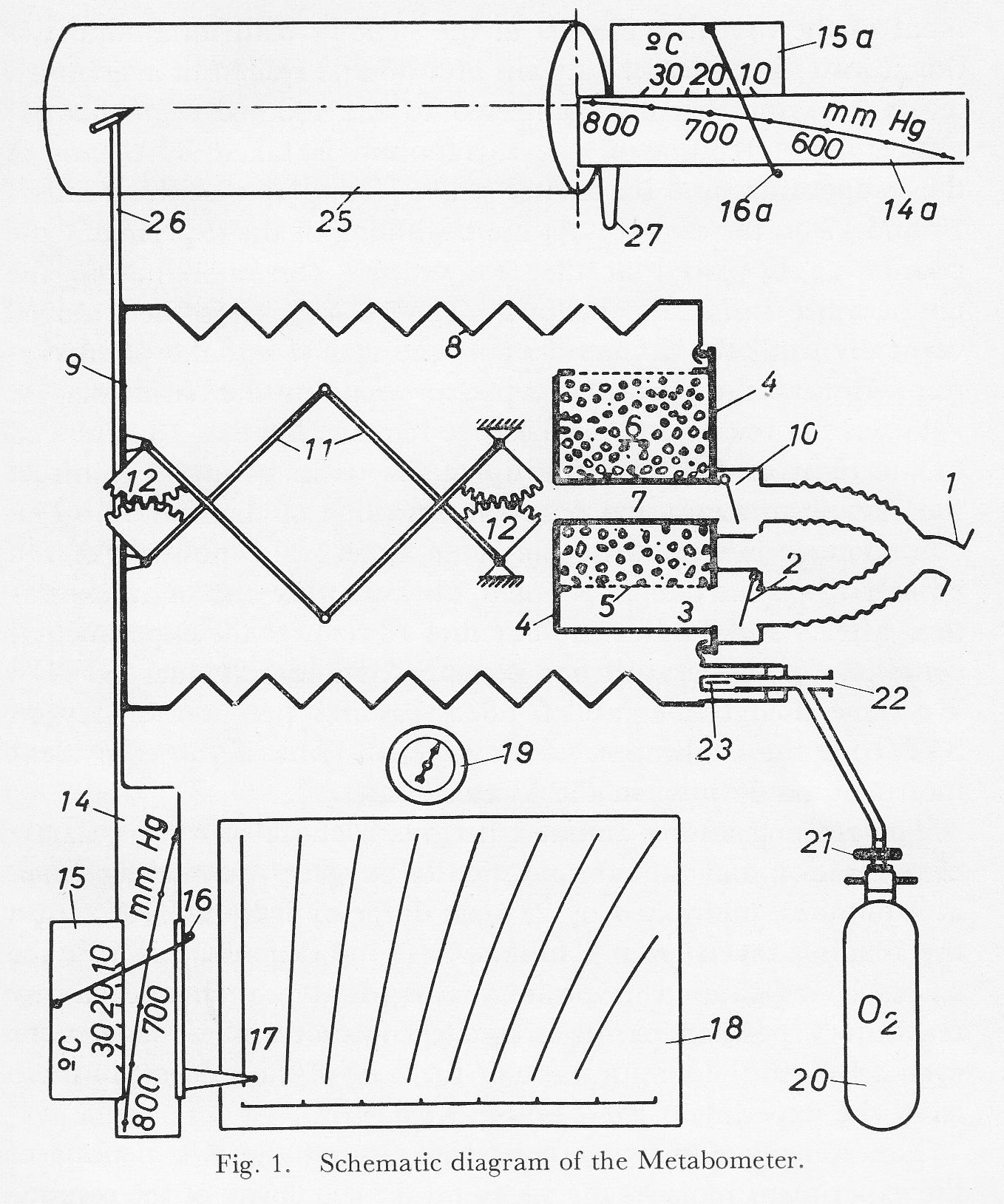
“Fig. 1 gives a schematic representation of the instrument. From the mouth piece 1 the expired air is directed through the corrugated tube into the lower part 3 of the soda lime container 4 through the valve 2. This air then passes through the stainless steel lattice 5 and the soda lime 6 and reached the bellows 8, thus displacing the movable plate 9 towards the left. At inspiration the air leaves through the central tube 7 and the valve 10, and returns to the mouth piece 1. The rectilinear and parallel movement of the movable plate 9 of the bellows with minimum frictional losses is assured by means of a double system of articulated levers 11 symmetrically connected to the toothed segments 12.
“The direct reading of the metabolism is taken by means of the temperature and barometer scales 15 and 14 and the pointers 16 and 17 on the dial 18. At the beginning of the experiment the pointer 16 is placed at the temperature corresponding to the temperature inside the bellows. The vernier 15 is then moved vertically until the pointer 16 cuts the scale 14 at the point corresponding to the atmospheric pressure read on the barometer 19.
“When the respiration has become regular, the dial 18 is moved to the right or left until the tip of the main pointer 17 falls at the end of an exhalation onto the zero line of dial 18. The chronometer is started at the same time. The position of the pointer 17 on the dial 18 is noted, always at the end of an expiration, after 4 and 8 minutes. The dial 18 reduced the experimental conditions of temperature and pressure to standard values (STPD). We have used the figure of 4.825 calories per liter of oxygen STPD for the calibration of the dial 18. This is equivalent most commonly used in the United States.
“The reading after 4 minutes permits a check of the regularity of respiration and the consumption of oxygen; the reading taken at 4 minutes multiplied by 2, must differ by less than 10% from the reading taken after 8 minutes. If the difference is 10% or more, it indicates a respiratory irregularity, a change in the respiratory position or an irregular consumption of oxygen, or even a leak in the mouth piece or the nose of the subject; in these cases the experiment must be repeated.”