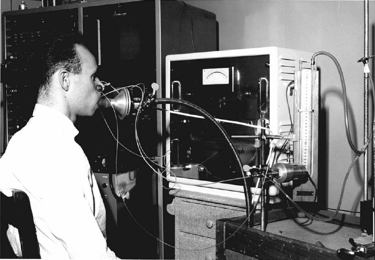
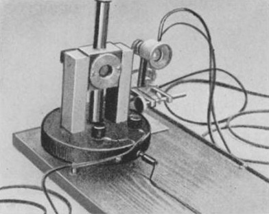
A Godart pneumotach system being used to measure pressure-volume curves. From a doctoral thesis, “Acute effects of inhalation of cigarette smoke on pulmonary mechanics” by John M. Miller, University of Edinburgh, Edmonton, Canada, 1963, page 18.
A Godart pneumotach system being used to measure pressure-volume curves. From a doctoral thesis, “Acute effects of inhalation of cigarette smoke on pulmonary mechanics” by John M. Miller, University of Edinburgh, Edmonton, Canada, 1963, page 18.
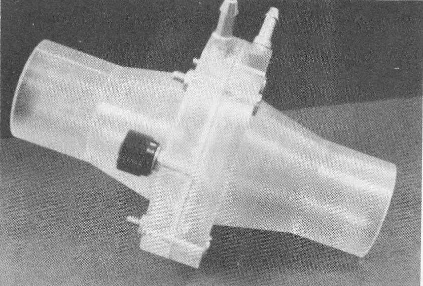
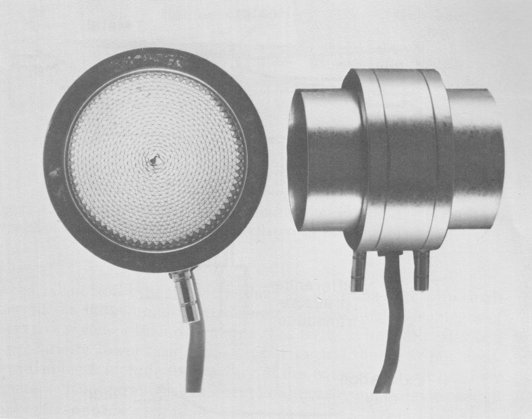
Manufacturer was not indicated. This is a heated pneumotach with is indicated by the black knob on the side which is actually the screw-on cover for an electrical post. From Medical Instrumentation for Healthcare, by Cromwell L, Arditti M, Weibell FJ, Pfeiffer EA, Steele B, Labok J. Published by Prentice-Hall, 1976. Page 267.
An amplifier and integrator for a Fleisch pneumotach. From “Pneumotachography” by W.M. Pols, Acta Anaesthesiologica Scandinavica, 1962, page 178.
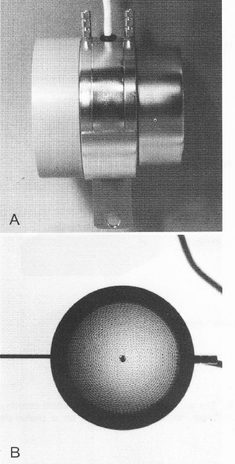
Side and front views of a Fleisch pneumotach. From “Pulmonary Function Testing: A Practical Approach” by Jack Wanger, published by Williams and Wilkins, 1992, page 14.
A Fleisch #3 pneumotach. From Office Spirometry. A practical guide to the selection and use of spirometers. By PL Enright and RE Hyatt. Published by Lea and Febiger, 1987. Page 79.
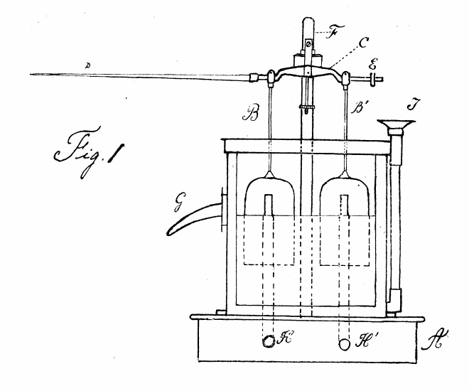
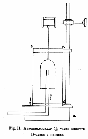
An early bi-directional flow sensor. From “Bijdrage tot de pharmacodynamica der respiratie.” By Evert van Kekem, Published by the University of Utrecht, 1905.
Two small plastic counterbalanced cups were suspended in a white spirit (alcohol?) bath (essentially small water-seal spirometers). Small tubes (H, H’) lead to each of them from either side of a pitot tube. Airflow through a pitot tube causes one side to rise and the other to fall. Which cup rises and which cup falls depends on the direction of airflow. The motion of the stylus (D) was roughly proportional to the flow rate.
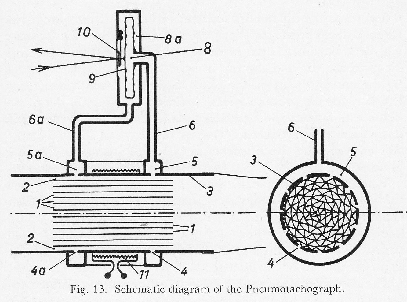
From “New methods of studying gaseous exchange and pulmonary function” by Alfred Fleisch, published by Charles C. Thomas, 1960, page 51.
“The great interest currently enjoyed by pneumotachography has induced us to improved our old instrument which separated the air flow into a number of parallel tubes 130 mm long and 1.8 mm interior diameter. The length of the air passages is now reduced to 32 mm, thus greatly decreasing the dead space. To improve the proportionality the inner diameter of the air passages is reduced to 0.8 mm.
“The system of air passages is obtained by rolling together a thin corrugated nickel strip and a flat strip (Fig. 13). The outer corrugated layer 2 is used for the pressure tappings. The brass tube 3 has two rows of small holes 4 and 4a distributed over its whole circumference and communicating with the annular ducts 5 and 5a. The pressure is the transmitted through the tubes 6 and 6a to the differential manometer 8. If the air flow passes through the pneumotachograph from right to left the pressure will be greater in 5 than in 5a; the membrane 9 will therefore move to the left and the ray of light will be deflect upwards by the mirror 10. If on the other hand the current passes fro left to right, the pressure will be greater in 5a than in 5, the membrane will move to the right and the ray of light will be deflected downwards. We would like to stress the fact that the membrane will only respond to differences in pressure, not to the absolute pressure.
“When the speed of the air flow does no exceed a certain value the air particles move in the pneumotachograph under laminar conditions, thus ensuring strict proportionality between speed and the deflection of the ray of light. One this limit has been passed a state of turbulence ensues, easily recognized by the slight oscillation of the light spot.
“The metallic membrane manometer connected to the pneumotachograph has a natural frequency of about 20 cycles per second; since the physiological oscillations of the air flow are slower, a rapid reaction and a reliable recording are assured.”
From Lehrbuch der Stimm und Sprachheilkunde (“Textbook of voice and speech therapy”), Chapter 1, “Die stimm und ihre Storungen” by Prof. Dr. R. Luchsinger, Published by Springer-Verlag, 1959, page 10. Manufacturer was not named.
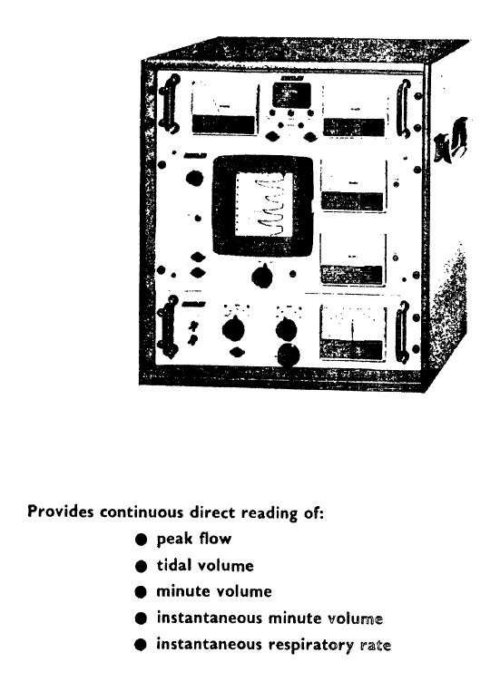
From a poorly photocopied product brochure on the Legacy Tobacco Documents website. Undated, but probably from the early 1970’s.
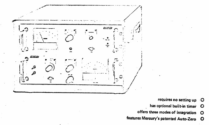
From a Mercury Electronics product brochure, found on the Legacy Tobacco Documents website. Undated, but likely from around 1970.