Category Archives: Diagram

Spirometer, Rebreathing system for altitude simulation, 1918, diagram

Spirometer_Rebreathing_System_Altitude_Simulation_1918_Diagram

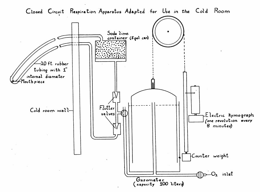
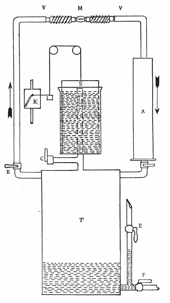
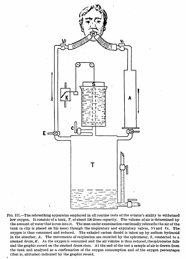
From: Manual of Medical Research Laboratory, United States School of Aviation Medicine, Randolph Field, Tex, United States. War Dept. Division of Military Aeronautics, U.S. Government Printing Office, 1918, page 214.

“The base of the machine is a steel tank (T) of 60 or 80 liters capacity, according to the type.  Type A has 80-liter, and types B and C 60-liter tanks. Air is inspired from the tank through the pipe at the left, and is expired back into the tank through the pipe and absorbing cartridge (A) at the right. The valves (VV) keep the air stream flowing always in the proper direction.  In order to maintain the contained air at approximately atmospheric pressure and to allow for changes in volume, a wet spirometer (S), carefully counterbalanced, is mounted on the tank and communicated freely with its interior through the vertical pipe (P). A stylus attached to the counterweight records the movements of the spirometer upon the smoked drum of the kymograph (K).  Water is admitted to the tank through valve (E) to replace the volume of the used oxygen and also to flush out the tank after an experiment. The water is drained away to the sewer by means of valve (F).  Valve (C) affords a free opening to the atmosphere for flushing the tank of the rebreathed air.  Valve (D) should invariably be closed while flushing the tank, otherwise wate will enter the absorption chamber (A) and ruin the cartridge.  The cartridge is a cylindrical paper tube filled with solid caustic soda, cast in thin shells so as to expose a large surface to the action of the gas.  IT is prepared for use in the machine by punching the ends full of quarter inch holes with a pencil.  The brass ring is then inserted in the lower end of the cartridge, the rubber ring fitted over the end, and the whole inserted into the absorption chamber.  Cartridges should never be used without both rubber ring and brass ring in proper position. Valve parts may be removed from the air valves (VV) by means of the brass spanner wrench, which, together with two new valve parts are furnished with each machine.  Counterweight slide rods should be frequently greased with vaseline and the pulleys oiled.  In setting up a machine care should be taken to level it properly, so the the inner can of the spirometer hands freely in the outer can and does not rub against the side.”
Gas Collection System, 1933

Gas_Collection_System_1933

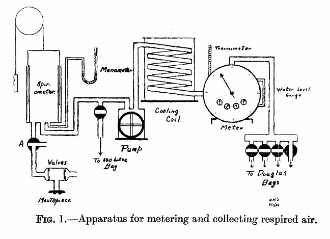
From: Solandt OM, Ridout JH.  The duration of the recovery period following strenuous muscular exercise.  Proceedings of the Royal Society of London, 1933: 113: 327-344, page 329.

“As shown in the diagram, the air expired by the subject is first collected in the 10-liter spirometer. From the spirometer it is pumped through a cooling coil, through the meter, and then into a Douglas bag.  In this way the air is metered before entering the bag, and the bag is only used to collect the air so that a sample may be taken.

“The valves used were of the conventional type, consisting of a circular rubber flap, seating on a metal ring. They were tested before each experiment. The pump used was of the movable blade rotary type and was driven by an electric motor. The meter used was a Sargent wet test gas meter. This type of meter is very sensitive to changes in water level, as Krogh (1929) has pointed out, hence the water level was checked before each experiment. The correct water level was determined by checking the meter against a small Bohr meter which has been calibrated by displacement of air. The accuracy of the Sargent meter was guaranteed by the makers to within 1 percent at rates of flow up to 50 cubic feet per hour.  During the experiments the rate of metering was never allowed to exceed this value. The cooling coil was used to prevent too great a rise in meter temperature owing to the passage of warm expired air through the meter. The effectiveness of this device is shown by the fact that the meter temperature seldom changed as much as one degree during an experiment (2 to 3 hours). By cooling the air, complete saturation with water vapor was also ensured.”

Helium Dilution Lung Volumes, 1949

Lung_Volumes_1949_Helium_Dilution

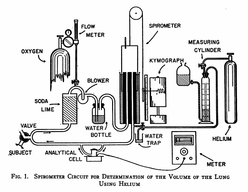
From: Meneely GR, Kaltreider NL.  The volume of the lung determined by helium dilution. Description of the method and comparison with other methords.  Journal of Clinical Investigaton, 1949 28(1): 129-139, page 130.

“The spirometer circuit is diagrammed in Figure 1.  The seven-liter cylindrical spirometer with obliterated internal dead space write the respiratory tracing on a kymograph drum. The volume of the spirometer may be read from the scale and pointer and, by transfer, from the respiratory tracing itself. The subject is connected to the circuit through a rubber mouthpiece on a three-way valve. The expired air passes vertically through a soda-lime canister for the most efficient absorption of carbon dioxide. Oxygen may be added at any desired rate through the diaphragm type flow control and meter on a tank of “medical” oxygen. A blower impels the expired air through the water bottle which contains many glass bead to break up the bubbles, and prevent disagreeable bumping due to large bubbles. Provision is made for the introduction of helium at the spirometer outlet. Part of the return flow shunts through the analytical cell and returns via the cell outlet to rejoin the return stream. The pressure differences in different segments of the circuit are small: slight negative pressure obtains between the soda-lime and blower, and positive pressure elsewhere. The soda-lime and the water bottle isolate the the blower to a degree, preventing vibration of the air column at the mouthpiece.”

Spirograph, Salter’s, 1865

Spirograph_Diagram_1865

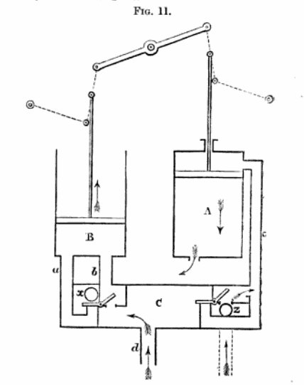
From: Lectures on Dyspnea, Lecture III.  By Hyde Salter, MD.  The Lancet London: A Journal of British and Foreign Medicine,  Surgery, Obstetrics, Physiology, Chemistry, Pharmacology, Public Health and News, Volume 2, October 28, 1865, page 475.

“The principle of the action of the instrument is this:  All the inspired air id derived from cylinder A, (above this piston) and all the expired air passes into cylinder B; (from culinder B it is again discharged into the open air; thus none passes back or is breathed over again.  The act of inspiration draws air from cylinder A expels the respired air from cylinder B, and the act of expiration which breathes the expired air into cylinder B draws a fresh supply of unbreathed air into cylinder A.”

Spirometer, Closed-circuit for Basal Metabolism, 1922

Spirometer_Closed_Circuit_Basal_Metabolism_1922

From: Spirometer measurement of oxygen consumption by the rebreathing method. By Charles Claude Guthrie, Archives of Internal Medicine, Volume 28, 1922, page 842.

“As is commonly known, the essential of rebreathing types of spirometers comprise a distensible closed space, as an elastic bag or spirometer; a supply of oxygen and means for introducing it into the apparatus; an absorber for removing carbon dioxide; a connection for a mouth or nose piece or mark; and means for measuring volume changes in the gas. The subject rebreathes for a definite period, usually ten minutes, and the volume change in the apparatus, after correction for pressure, temperature and water vapor, indicates the amount of oxygen consumed.”

“The spirometer shown in Figure 1. is very satisfactory.  It consists of a vital capacity type of spirometer (floating bell form, Fig. 1, A), a soda-lime carbon dioxide absorber (Fig 1., B), a four-way tap (Fig 1., C), a gas mixing pump (Fig. 1, D) and a tank of oxygen.

“The three point suspension of the bell is very desirable. The bell moves vertically with little side sway or rotation and the scale, which is attached to the bell, remains directly behind the reading sight.  The sight (Fig 1, E) is adjustable and may be set instantly against the zero mark of the scale. The scale on one side is numbered from below upward, so that the final reading directly represents the oxygen consumed, no other subtractions or calculation being required.  The smallest scale divisions represent 20 cc.”

Valve for basal metabolism spirometer, 1922

Valve_Spirometer_Closed_Circuit_Basal_Metabolism_1922

From: Spirometer measurement of oxygen consumption by the rebreathing method. By Charles Claude Guthrie, Archives of Internal Medicine, Volume 28, 1922, page 843.

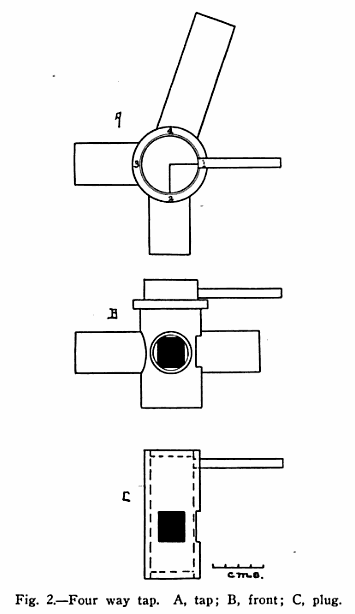
“The tap (Fig. 2) serves to connect the spirometer through the absorber with the pump, the subject or the outside air.  The rotating portion of the tap is hollow and provided with two openings spaced 90 degrees apart.

“In the first position of the tap, the absorber is shut off and the subject breathes room air.  Position two is a quarter turn (clockwise, i.e. to the right) and switches the subject to the absorber and thus to the air in the spirometer, at the same time closeing the opening to the outside.  Position three connects the absorber with the pump, and position four connects the pump to the outside air.”

Pitot Flow Sensor, 1904, End-view

Pitot_Flow_Sensor_1904_End_View

From: Die Geschwindigkeith des Athemstromes und das Athemvolum des Menschen, by H. Zwaardemaker and C.D. Ouwehand, Archiv für Anatomie und Physiologie, Volume 28, Published by Physiologische Gesellschaft zu Berlin, 1904, page 243.

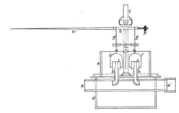
An early flow measuring device.  When a subject blew through the central tube (a), positive and negative pressure in the opposed pitot tubes (b) caused thin plastic domes (f) to rise or fall. Their movement was transferred to a long, counter-balanced pen which traced a curve on a smoked drum.

Pitot Flow Sensor, 1904

Pitot_Flow_Sensor_1904_Side_View

From: Die Geschwindigkeith des Athemstromes und das Athemvolum des Menschen, by H. Zwaardemaker and C.D. Ouwehand, Archiv für Anatomie und Physiologie, Volume 28, Published by Physiologische Gesellschaft zu Berlin, 1904, page 243.

An early flow measuring device.  When a subject blew through the central tube (a-a’), positive and negative pressure in the opposed pitot tubes (b-b) caused thin plastic domes (f-f) to rise or fall. Their movement was transferred to a long, counter-balanced pen which traced a curve on a smoked drum.