During this time period pulmonary medicine was primarily concerned with tuberculosis. Pulmonary physicians were mostly interested in X-rays, medications, therapeutic pneumothoraxes, and sanitariums, and had only minimal interest in spirometry and other pulmonary function tests. Advancements in pulmonary function testing came primarily from endocrinologists and physiologists, and it is through them that during this time period spirometers found new uses in Basal Metabolic Measurements (BMR), Exercise Testing, Hypoxia Challenge testing, Nitrogen Washout Lung Volumes, Maximum Minute Ventilation (MVV), and Hydrogen and Helium Dilution Lung Volumes.
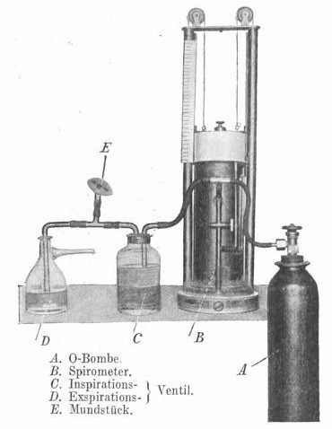
Minute Ventilation Measurements from 1914. From: Handbuch der Tuberkulose, Volume 2, 1914, Inhalationstherapie, by J. Lazarus and E. Aron, page 438. A system for measuring ventilation. D and C are Muller valves for unidirectional flow. The spirometer is a more-or-less exact copy of the Hutchinson spirometer.
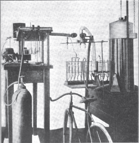
Exercise Testing, 1915. Described in text as a 30 liter recording spirometer. From: Boothby WM. The determination of the circulation rate in man at rest and in work. Amer J Physiol, 1915, v37, p383.
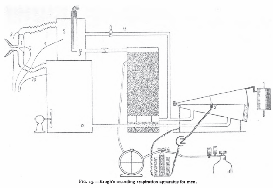
Krogh Spirometer system for Basal Metabolism Measurements, 1916. From: The respiratory exchange of animals and man by August Krogh, 1916, page 40.
“Krogh’s apparatus (fig. 15) [1913] which is a modification of an instrument constructed by Haldane and Douglas [1912], is furnished with valves and the air is circulated by the respiratory movements of the subject. Carbon dioxide is absorbed in a vessel containing a charge of soda lime sufficient to absorb 1000 liters of carbon dioxide, a quantity produced by a man at rest in about 70 hours. The recording spirometer gives a quantitative record of the respiratory movements and governs the admission of oxygen by closing an electric circuit at (5). The oxygen from the cylinder is measured by the meter which records electrically by closing a circuit each time a certain quantity has been admitted. Whenever an experiment has to be extended over a long period, or if the absorption of oxygen is very rapid as during heavy muscular work, the oxygen admitted must be nearly pure to prevent the oxygen percentage in the small apparatus from falling.
“The apparatus in its present form does not allow the direct determination of carbon dioxide. When such determinations are desired samples of expired and inspired air are drawn from the vessels (2) and (10). The respiratory quotient is determined by analysing these samples for carbon dioxide and oxygen. The total respiratory exchange can also be measured over short periods by by multiplying the analytical results by the ventilation as measured from the graphic record.”
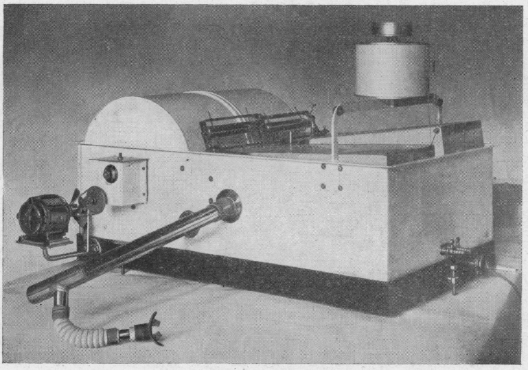
Hypoxia Testing System, 1920. From: The examination and classification of aviators with special reference to the effects of high altitiude. By JF Grant, California State Journal of Medicine, 1920, page 99.
“The Henderson Rebreathing Apparatus has been perfected for such tests [low O2 at altitude]. During the test the subject breathes the air in the tank. He sits with a clip placed on the nose and comfortably adjusted mouthpiece in the mouth, which is suitably connected by means of inch rubber tubing with light automatic valves. He inhales the air through the respiratory valve and exhales through the expiratory valve into a cartridge containing an absorbant for carbon dioxide , namely sodium hydroxide in cake form. The exhaled air is thus freed from carbon dioxide as it is returned to the tank. A spirometer compensates for changes in volume and writes a record of the respiration on the revolving drum of a kymograph. By this arrangement the subject continues to rebreathe the air in the tank, from which he gradually absorbs oxygen. As the percentage of oxygen decreases, the subject, in effect physiologically, is slowly ascending to higher altitudes. The volume of air rebreathed is sufficient to require between 25 and 30 minutes to lower the amount of oxygen to 8 or 7 percent, which is equivalent to altitudes of 25,000 to 28,000 feet.”
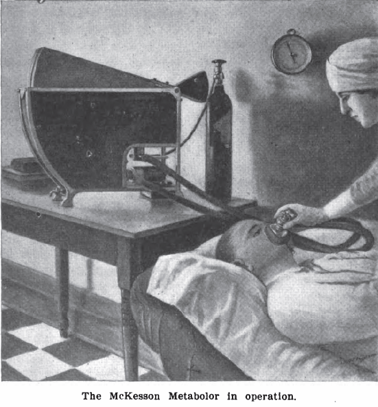
McKesson Metabolor, 1921. Measured Basal Metabolism. It was a variation of a Krogh Spirometer. From: International Journal of Surgery, 1921, Volume 34. Page 261.
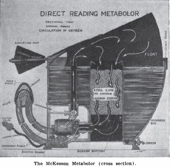
McKesson Metabolor cross-section, 1921. Measured Basal Metabolism. It was a variation of a Krogh Spirometer. From: International Journal of Surgery, 1921, Volume 34. Page 260.
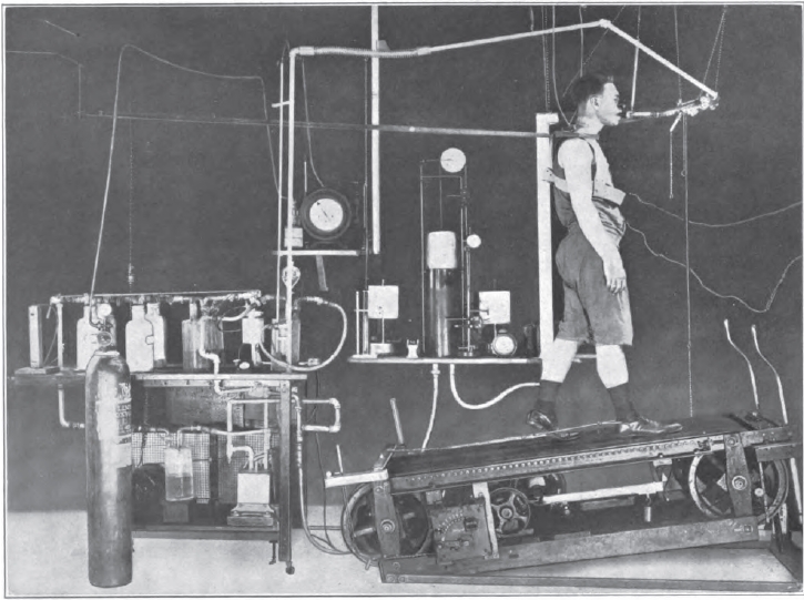
Exercise Testing, 1922. From: Gaseous Exchange and physiological requirements for level and grade walking, by Henry Monmouth Smith, 1922, Frontpiece.
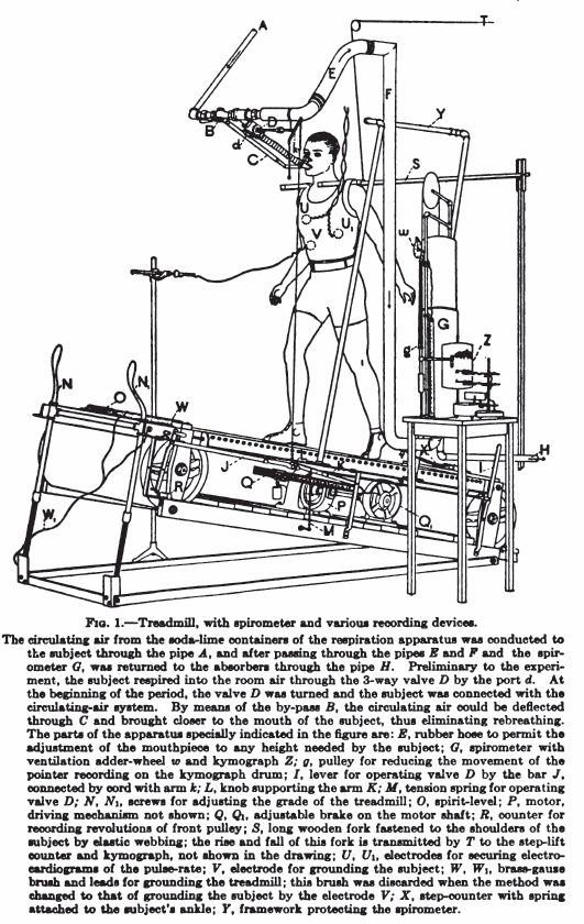
Exercise testing system, 1922. From: Gaseous exchange and physiological requirements for level and grade walking, by Henry Monmouth Smith , 1922, page 19.
Dual Krogh Spirometer for Basal Metabolism Measurements, 1924. From: CLXXII: An apparatus for the graphical recording of oxygen consumption and carbon dioxide output, especially adapted for clinical work. By H.C. Hagedorn. Biochemical Journal, 1924, page 1304.
“Figure 2 shows the apparatus in a convenient form which has been in use for about two years with complete satisfaction. The gas meters and spirometers are arranged in a common water-bath, the spirometers recording on a common drum, most conveniently with ink of different colours. The water-bath is fitted with an overflow tube to secure constant water level; it contains about 100 kg. water, and the expired air is led through a pipe of considerable length which is immersed in the bath to cool the air to the temperature of the bath before it enters the gas meter. From the service pipe to the spirometer (B) there is a wide pipe to secure that every change in air pressure caused by the respiration is taken up promptly by the spirometer (B), so that there can be an absolutely constant in the gas meter I.
“The accuracy of the results largely depends on the care with which the spirometers are balanced; every change in the air pressure in one of the spirometers will affect the water level in the corresponding gas meter and so disturb its accuracy. The spirometers are therefore arranged on special bearings and balanced with a double set of counterbalances, a large one for gross and a small one for fine adjustment. The counterbalances are adjustable horizontally and vertically, thus allowing convenient compensation for buoyancy of the spirometer.”
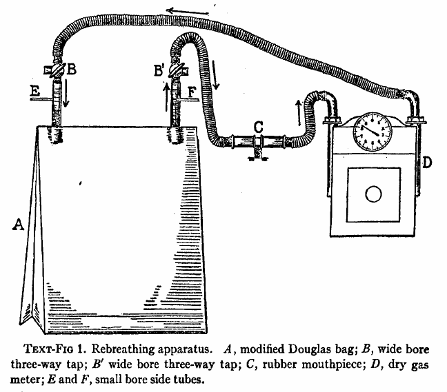
A Douglas Bag and gas meter used to measure CO2 response, 1925. From: The respiratory response to carbon dioxide. By HW Davies, GR Brow, CAL Binger. Journal of Experimental Medicine, 1925, page 38.
“The effect of gradually increasing percentages of carbon dioxide was studied by means of rebreathing in a closed circuit consisting of a modified Douglas Bag with inflow and outflow tubes, a dry meter, and a rubber mouthpiece fitted with inspiratory and expiratory valves. The general arrangement of the apparatus is shown semidiagrammatically in text-fig. 1. The direction of airflow is indicated by means of arrows. A is the modified Douglas Bag of 100 liters capacity. B, B’ are wide bored three-way taps. C is the mouthpiece. D is a twenty-light capacity “B-type” dry meter manufactured by D. MacDonald and company of Albany. The resistance of this meter is almost negligible even at the maximal rates of pulmonary ventilation produced by high percentages of carbon dioxide in the inspired air. E is a small bore side tube connected with an oxygen tank fitted with reducing valve and a flow meter calibrated with approximate accuracy rates of flow of less than 1 liter per minute. A similar side tube, F, is used to obtain samples of inspired air, either into exhausted sampling tubes or directly into the burette of the Haldane gas analysis apparatus. By way of the three-way stop cocks B,B’ the subject may be made to inhale from and exhale into the room air through the meter, and his normal respiratory rate and minute volume may be determined. When the stop-cocks are turned the apparatus becomes a closed circuit, inspiration and expiration being from and to the Douglas Bag, A.”
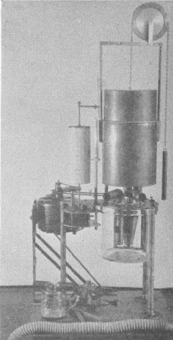
Portable Calorimeter for the measurement of Basal Metabolism, 1926. From: A portable calorimeter for the determination of both oxygen and carbon dioxide. JF McClendon, GJ Humphrey, MM Loucks. Journal of Biological Chemistry, 1926; 69: 513-517.
“The apparatus consists of a spirometer holding 6 liters and with a recording drum of such size that charts purchased from the Sanborn Corporation may be used to record the respirations. The bell is counterpoised by a chain and weight passing over a wheel on which the liters of oxygen in the bell may also be read if desired. Below the spirometer is a museum jar holding 6 liters in which is placed a standard solution of Ba(HO)2 containing BaCL2 to reduce hydrolysis and 0.1 gm. phenolphthalein, A synchronous alternating current electric motor drives a clock work revolving the recording drum and at the same time drives a centrifugal pump which sprays the Ba(HO)2 in the museum jar. The pump is made off a inverted, truncated hollow cone. The cone is open above and below and is provided with radial baffles or septa which allow passage of the fluid upwards but force the fluid to rotate with the cone. The rotation of the cone causes the fluid to be sucked up from the bottom and sprayed out at the top at a very rapid rate in order to absorb the CO2 out of the air.
“In the use of the apparatus a mask or mouthpiece is applied to the patient, having a 1 inch side outlet which allows free breathing to the outside until the moment of beginning the experiment. A 1-1/4 inch bore rubber tube leads to a brass tube of the same bore going down just below the level of the Ba(HO)2 solution in the museum jar, admitting expired air into the jar. The passage of the tube below the solution, acting as a valve, prevents reversal of the air current. From the museum jar a vertical tube rises up through the water in the spirometer. Another 1-1/4 inch brass tube comes down through the water of the spirometer and passes to the outside where it is connected with a valve and then to a 1-1/4 inch rubber tube to the mask over the patient’s face. This tube brings oxygen from the spirometer to the mask and the valve prevents reversal of the current. The apparatus is mounted on a stand of sufficient height to allow the museum jar to be raised up in place and clamped to the plate of the apparatus with six clamps, being made air-tight by a rubber gasket. In operation after the mask is applied (the bell having been filled with oxygen and the Ba(HO)2 solution having been introduced) the motor is started causing a base line to be written on the recording drum and the Ba(HO)2 rapidly sprayed in the museum jar. The patient is watched until the respirations become regular; then the side outlet to the mask is closed with a rubber stopper and the color of the Ba(HO)2 solution is carefully watched. As soon as the phenolphthalein is decolorized, the stopper to the side outlet of the mask is withdrawn, thus ending the experiment. The motor may be stopped and the mask removed at leisure.”
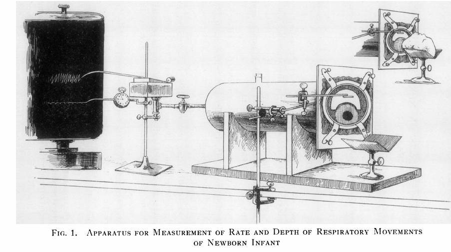
Infant Plethysmograph, 1931. From: J Clin Invest. 1931 August; 10(3): 545–558, BREATHING MEASUREMENTS ON NORMAL NEWBORN INFANTS, Douglas P. Murphy and Edward S. Thorpe, Jr.
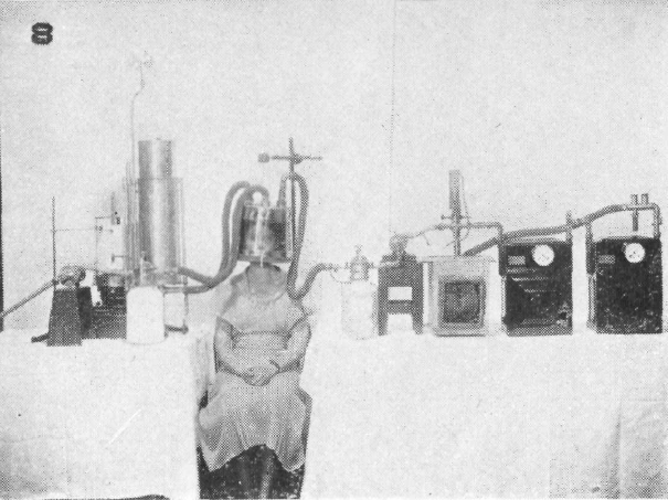
Open-circuit respiration apparatus with helmet used for BMR measurements, 1933. Taken from: The Development of Methods for Determining Basal Metabolism of Mankind Carpenter, Thorne M. The Ohio Journal of Science. v33 n5 (September, 1933), 297-314
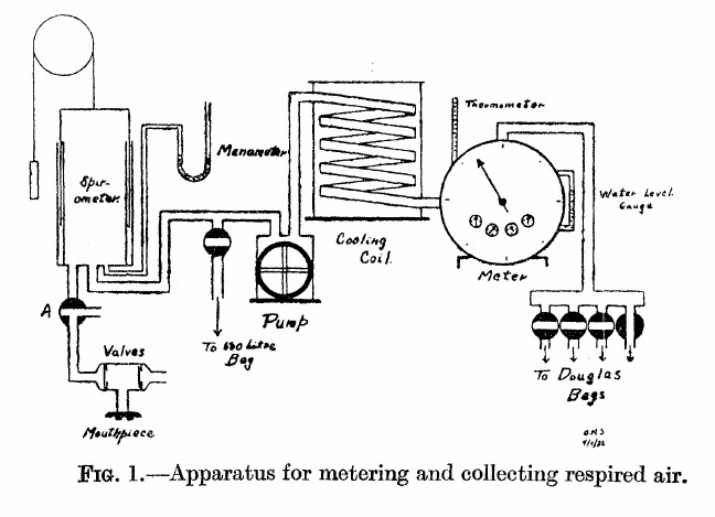
Gas Collection System for Exercise Testing, 1933: From: Solandt OM, Ridout JH. The duration of the recovery period following strenuous muscular exercise. Proceedings of the Royal Society of London, 1933: 113: 327-344, page 329.
“As shown in the diagram, the air expired by the subject is first collected in the 10-liter spirometer. From the spirometer it is pumped through a cooling coil, through the meter, and then into a Douglas bag. In this way the air is metered before entering the bag, and the bag is only used to collect the air so that a sample may be taken.
“The valves used were of the conventional type, consisting of a circular rubber flap, seating on a metal ring. They were tested before each experiment. The pump used was of the movable blade rotary type and was driven by an electric motor. The meter used was a Sargent wet test gas meter. This type of meter is very sensitive to changes in water level, as Krogh (1929) has pointed out, hence the water level was checked before each experiment. The correct water level was determined by checking the meter against a small Bohr meter which has been calibrated by displacement of air. The accuracy of the Sargent meter was guaranteed by the makers to within 1 percent at rates of flow up to 50 cubic feet per hour. During the experiments the rate of metering was never allowed to exceed this value. The cooling coil was used to prevent too great a rise in meter temperature owing to the passage of warm expired air through the meter. The effectiveness of this device is shown by the fact that the meter temperature seldom changed as much as one degree during an experiment (2 to 3 hours). By cooling the air, complete saturation with water vapor was also ensured.”
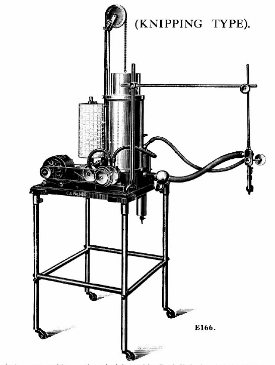

Knipping closed-circuit apparatus for measuring VO2 and VCO2, 1934. From Palmer, C. F. 1934. Palmer Research and Students’ Apparatus for Physiology, Pharmacology, Psychology, Bacteriology, Phonetics, Botany, etc.: Manufactured by C. F. Palmer (London) Ltd., Myographic Works, 63a, Effra Road, Brixton, London, S.W. 2. England, page 87 & 88.
“Very briefly the circulation system is as follows: Gas is from from the Spirometer A, which has previously been charged with oxygen, into the Pump P, and foced from there down the centre tube of the flask F, and through the K.O.H. where the CO2 produced is absorbed, and so to the three-way cock T.C, and the mouthpiece H, from thence it returns through the safety valve S.V. to the Spirometer A. The reduction in volume due to the amount of oxygen consumed, is registered by the ink pen W, on the calibrated chart affixed to the recording cylinder D.
“On order to ascertain the amount of CO2 produced, the subject at the mouthpiece H should be disconnected from the apparatus by the three-way cock TC, the air should continue to be circulated in the apparatus until the pen W records a horizontal line. The H2SO4 is then run slowly into the K.O.H in the flask F, through the cock C. Cooling is effected by the water in a cylindrical tank around the outside of the flask.
“The action of the H2SO4 on the K.O.H. causes the C.O2 absorbed to be given off, and so the float of the Spirometer rises, the amount being recorded by the ink pen W.

Knipping Spirometer system for lung volumes, 1939. From: F. J. C. Herrald and J. McMichael. Determination of Lung Volume: A Simple Constant Volume Modification of Christie’s Method, Proc. R. Soc. Lond. B 1939 126, February 1939
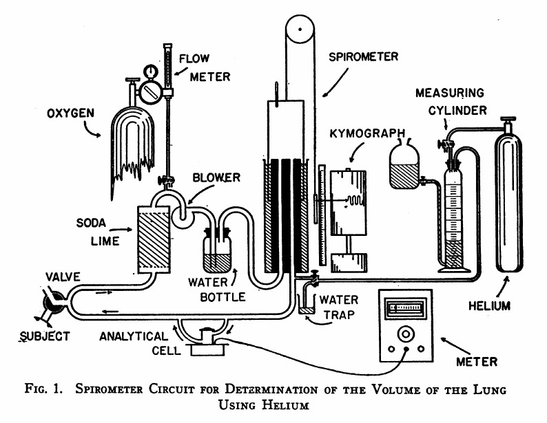
Helium Dilution FRC, 1949: From: Meneely GR, Kaltreider NL. The volume of the lung determined by helium dilution. Description of the method and comparison with other methords. Journal of Clinical Investigaton, 1949 28(1): 129-139, page 130.
“The spirometer circuit is diagrammed in Figure 1. The seven-liter cylindrical spirometer with obliterated internal dead space write the respiratory tracing on a kymograph drum. The volume of the spirometer may be read from the scale and pointer and, by transfer, from the respiratory tracing itself. The subject is connected to the circuit through a rubber mouthpiece on a three-way valve. The expired air passes vertically through a soda-lime canister for the most efficient absorption of carbon dioxide. Oxygen may be added at any desired rate through the diaphragm type flow control and meter on a tank of “medical” oxygen. A blower impels the expired air through the water bottle which contains many glass bead to break up the bubbles, and prevent disagreeable bumping due to large bubbles. Provision is made for the introduction of helium at the spirometer outlet. Part of the return flow shunts through the analytical cell and returns via the cell outlet to rejoin the return stream. The pressure differences in different segments of the circuit are small: slight negative pressure obtains between the soda-lime and blower, and positive pressure elsewhere. The soda-lime and the water bottle isolate the the blower to a degree, preventing vibration of the air column at the mouthpiece.”

PFT History by Richard Johnston is licensed under a Creative Commons Attribution-NonCommercial 4.0 International License.