From “Methods in pulmonary physiology”, by Bertels H, Bucherl E, Hertz CW, Rodewald G, Schwab M. Translated by Workman JM. Hafner Publishing Co., 1963, page 31. Undated, but probably from around 1950.
From “Methods in pulmonary physiology”, by Bertels H, Bucherl E, Hertz CW, Rodewald G, Schwab M. Translated by Workman JM. Hafner Publishing Co., 1963, page 31. Undated, but probably from around 1950.
From “Methods in pulmonary physiology”, by Bertels H, Bucherl E, Hertz CW, Rodewald G, Schwab M. Translated by Workman JM. Hafner Publishing Co., 1963, page 26.
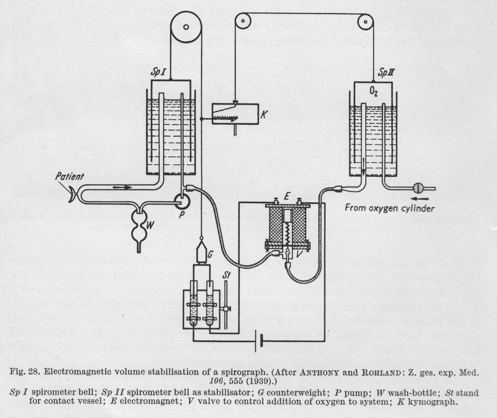
“Anthony and Rohland were the first to use an electro-magnetic device. In this apparatus, the addition of oxygen is dependent on the expiratory position. The counterweight of the spirometer bell dips into a vessel of mercury, so arranged that at the highest position of the spirometer (expiratory position) an electrical circuit is closed, resulting in the addition of oxygen through a valve operated by an electro-magnet. The loss in volume of the O2 gasometer (the second spirometer bell) is recorded providing a measure of the O2 consumption. The ventilation tracing is horizontal.”
From “Methods in pulmonary physiology”, by Bertels H, Bucherl E, Hertz CW, Rodewald G, Schwab M. Translated by Workman JM. Hafner Publishing Co., 1963, page 39.
From “Methods in pulmonary physiology”, by Bertels H, Bucherl E, Hertz CW, Rodewald G, Schwab M. Translated by Workman JM. Hafner Publishing Co., 1963, page 42.
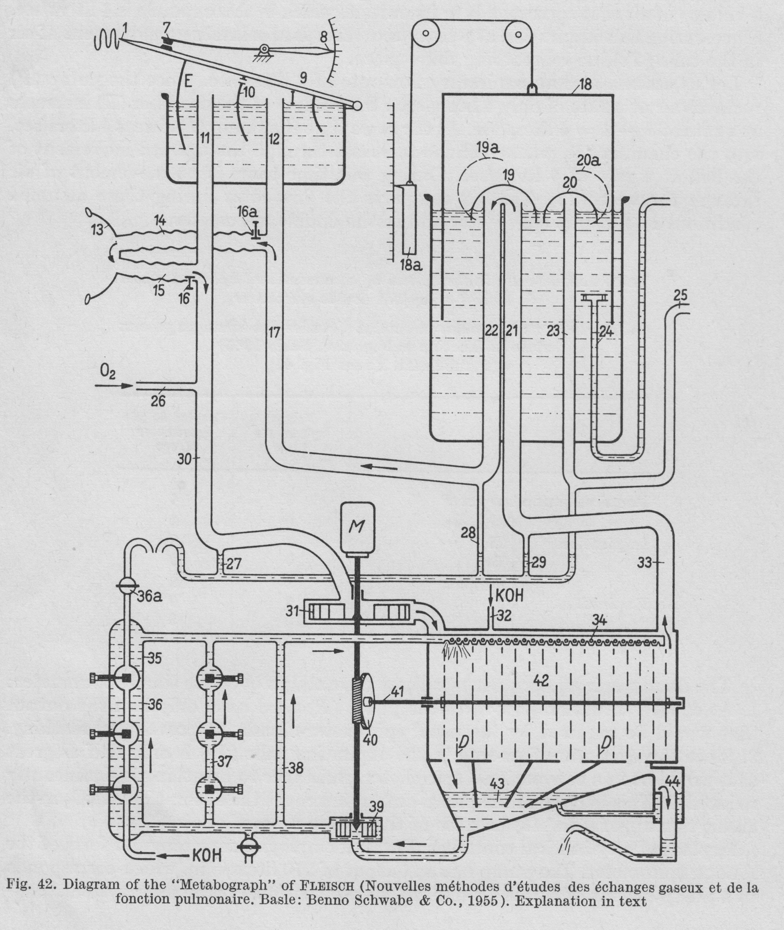
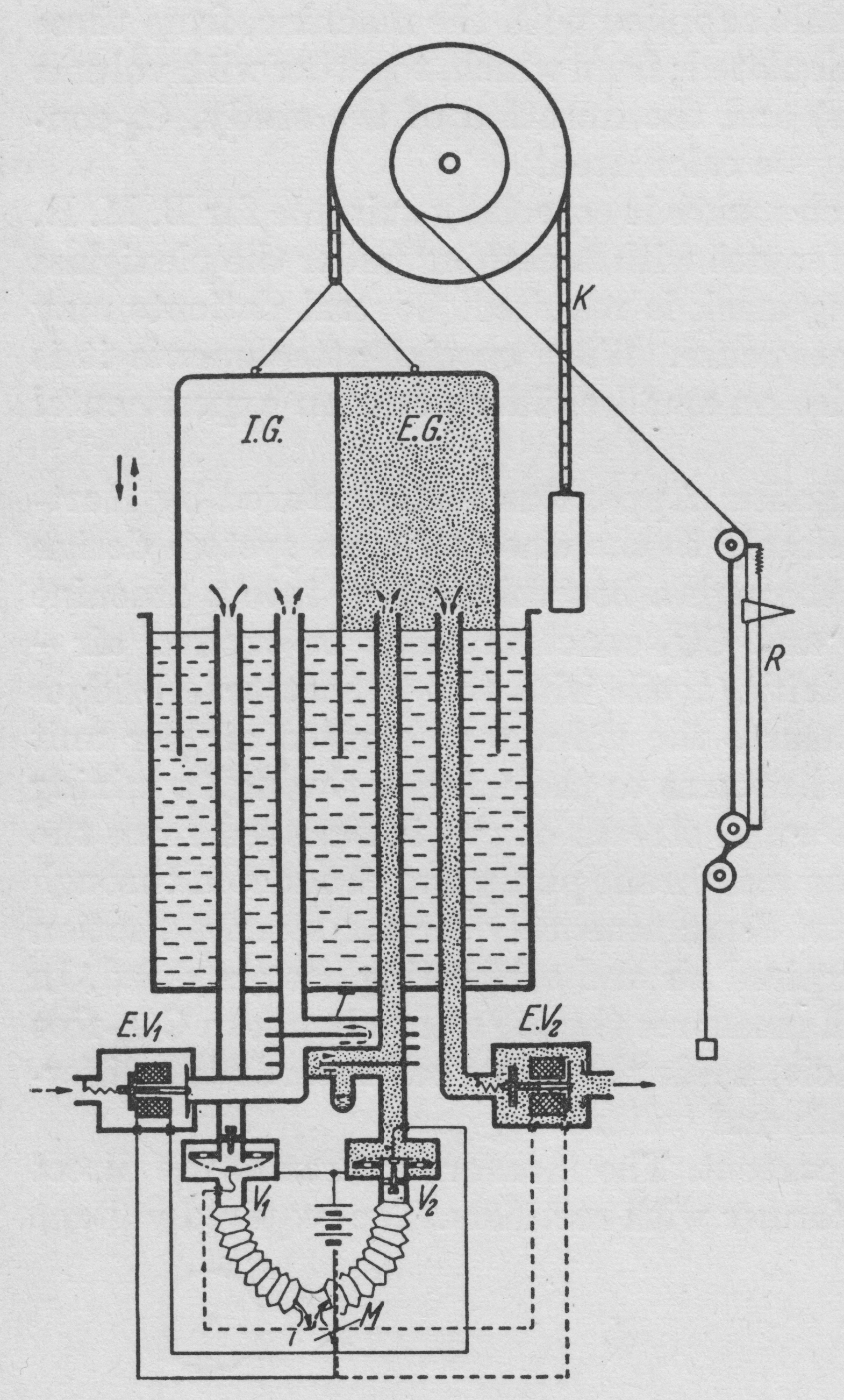
“Figure 42. is a diagrammatic representation of the construction of the apparatus. A motor (M) drives the pump (31), which sends air int the CO2 abdorbant chamber (42). Freed of CO2, the air passes by way of the tube (33) into (21), then under the valve (19). From here it is led through tubes (22), (17), (14), (15), (30) and returns to the pump (31). During inspiration the bell (9) of the double spirometer sinkes and a corresponding volume of air passes out of (I) through tubes (12) and (14) into the lungs, while the pump removes an equal volume from the chamber (E) through tubes (11), (30). During expiration, the volume of air that leaves the lungs travels by way of (15) and (11) to chamber (E), while the corresponding volume passes into chamber (I) through (17) and (12). This the bell (9) rises. The partitioning septum (10) is pierced by a small opening so that some air is always passing from chamber (I) into chamber (E), preventing accumulation of CO2.
“Volume stabilization is achieved through an electrical contact (7). When contact is broken, oxygen is added to the system by a pump through (26). This establishes the bell in the middle position, and maintains the O2 concentration in the system practically constant. When the bell touches the contact (7), the total volume of the system is 32 liters.
“In the absorption chamber (42) there are rotating discs, over which KOH runs. This arrangement provides the larges possible surface area for CO2 absorption. The KOH is collected in a sump (43), removed hence by a pump (39) and sent back to the distribution chamber (34) by three parallel routes (38), (37) and (36). Recording of CO2 production is based on the measurement of the electrical conductivity of the KOH. Throughout the period of study the conductivity of the KOH is held constant. When the degree of alkalinity of the KOH is reduced by the expired CO2 resulting in reduced conductivity, fresh KOH is added through the side tube (32) until the original conductivity is restored. Thus the CO2 production of the subject under study is determined directly by the amount of fresh KOH that has been added.”
From “Methods in pulmonary physiology”, by Bertels H, Bucherl E, Hertz CW, Rodewald G, Schwab M. Translated by Workman JM. Hafner Publishing Co., 1963, page 50.
“An alternative method of making spirographic recordings from an open system by deloped by v. Tavel. A double spirometer is employed. The partition inside the spirometer bell separate the inspired from the expired air. The subject is connected to the apparatus by a mouthpiece or breathing mask. The course of the air is directed by valves V1 and V2. On inspiration air is withdrawn from the inspiratory section. On expiration air passes to the expiratory section. The tow controlling valves V1 and V2 control through corresponding contacts the opening and closing of the electromagnetic valves EV1 and EV2. On inspiration (when V1 is open) EV1 is closed and EV2 is opened. Thus during inspiration the bell sinks and air from IG enters the lungs, while the gas in EG passes through to the outside through EV2. On expiration (when V2 is open) EV1 us opened and EV2 is closed. This the bell rises during expiration because expired air passes into EG, and at the same time a corresponding volume of room air is drawn into IG through EV1. A system of coils T (heat exchanger) equalises the temperature of room air and expired air. The movements of the spirometer bell are recorded in the usual way on a kymograph. Since normally CO2 output is less than O2 uptake (RQ < 1), in this system there is a fall in the level of the bell which is proportional to the respiratory quotient (when RQ = 1, the course of the ventilation tracing is horizontal since the inspiratory and expiratory volumes are equal). Expired air may be collected for analysis in a Douglas bag attached distal to the valve EV2. Since the minute volume of ventilation is recorded on the kymograph and the respiratory quotient can be determined by the slope of the ventilation tracing, analysis of the CO2 concentration of expired air is all that is necessary for CO2 output and O2 uptake.”
From a Fenyves & Gut sales brochure kindly provided by Emanuele Isnardi.
“One possible extension of the S basic unit is designed to determine the gas exchange or G or perform ergospirography, respectively, this representing a SG assembly. Unlike rival products this unit operates without valves, i.e. under optimum physiological conditions. For it should be noted that there are still systems on the market which require the subject to inhaled through a mask fitted with inspiration valves and exhale through a hose fitted to the mask. Of course such systems cannot work satisfactorily since they involve inspiration valves and because dead-space air is re-inhaled from the expiration hose. Our system has overcome these drawbacks.
Principle of measurement: the expired gases are continuously drawn off while changes in concentration levels occur. However, the average values necessary for further processing (e.g. O2 uptake) are drawn off in proportion to the expiratory flow rate by a special pump of our own design which can be modulated very rapidly. The expirate is then stored in a small collecting vessel. The resulting weighted samples are then analyzed in on-line analyzers for their O2 and CO2 concentrations (ΔFO2 and ΔFCO2 respectively).
Essentially the G apparatus consists of a slide-in unit for extraction proportionate to the flow of respiratory gases during expiratory phases. A device for averaging and converting the pulsating gas flow to a steady state required by the analyzers is included. The necessary equipment comprises O2 and CO2 and, optional, N2 analyzers (see under A), as well as a multi-channel compensated direct recorder (see under R). We recommend our slide-unit for determining the MV directly (unnecessarily if the assembly includes a computer) because it no only reduces working time, but also compensated for the time-lag occuring between the ΔFO2 and respectively, ΔFCO2 quantities on the one hand, and the minute volume on the other.”
From a Fenyves & Gut sales brochure kindly provided by Emanuele Isnardi.
“We supply an economical analogue computer with permanent wiring for the automatic computation of parameters if immediate interest to the physician (MVBTPS, VO2STPD, VCO2STPD, RQ, respiratory equivalent RE, VO2/PR, f, caloric production). This computer which may be acquired in three stages processes all data provided by the S and G assemblies according to the exact formulae reduced to the usual gas conditions and taking into account atmospheric pressures and the time-lag between sensing ventilatory activity and the determination of gas exchange values.
Data output by printer and/or 12 channel point plotter.”
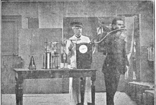
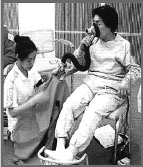
Using a Chauveau valve, the subject’s exhaled volume is measured by a gas meter and analyzed for CO2 and O2 chemically. Found in “The Human Motor, Or, The Scientific Foundations of Labour and Industry” by Jules Amar, Elsie Mary Butterworth, George E. Wright, published by G. Routledge & sons, Limited, 1920, page 145, but was ascribed to Jules Amar, Journal de Physiologie, March 1911, page 212.
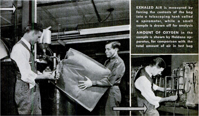
Douglas bag used to measure oxygen consumption in altitude research. From Popular Science Magazine, May 1942. “How flyers are redesigned. Air Surgeons groom men for survival at high altitude”, page 117.