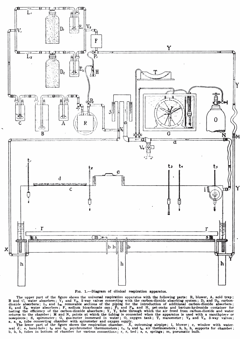
From: Respiratory exchange with a description of a respiration apparatus for clinical use, Part II. Boston Medical and Surgical Journal, June 22, 1916, pp 898-909, by Frances G. Benedict and Edna H. Tompkins. Diagram from page 906.
From: Respiratory exchange with a description of a respiration apparatus for clinical use, Part II. Boston Medical and Surgical Journal, June 22, 1916, pp 898-909, by Frances G. Benedict and Edna H. Tompkins. Diagram from page 906.
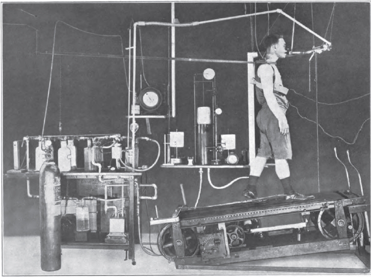
From: Gaseous Exchange and physiological requirements for level and grade walking, by Henry Monmouth Smith, 1922, Frontpiece.

From: Textbook of human physiology by Leonard Landlois, 1889, page 228.
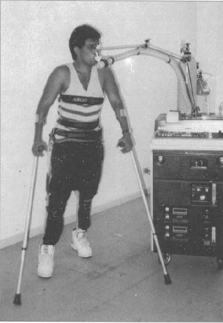
A Beckman Metabolic cart in use in a study on exercise patients with spinal cord injuries. From: Muszkat R, Yazbek P, Arango CT, Moreira MC, Trombetta IC, Battistella LR. Assessment of functional capacity during gait using a reciprocal propulsion orthosis (ARGO) – a comparative study with a conventional mechanical orthosis. Sao Paolo Medical Journal, 1994, 112(1): page 496.
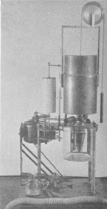
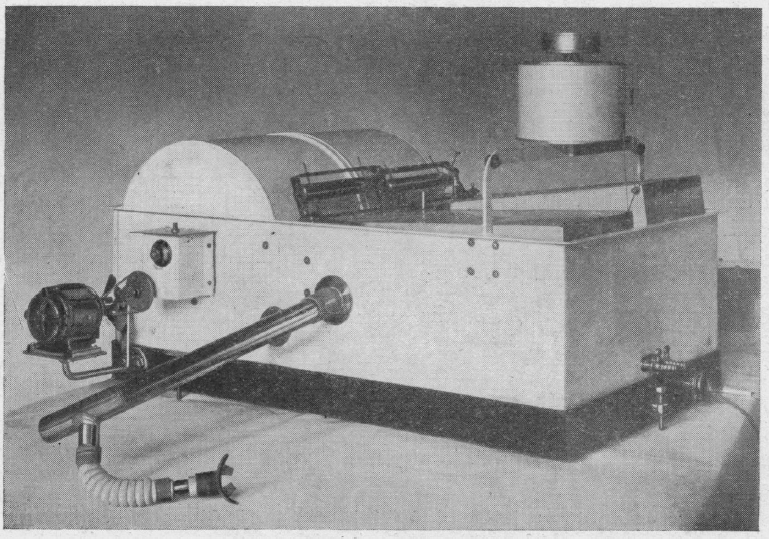
From: A portable calorimeter for the determination of both oxygen and carbon dioxide. JF McClendon, GJ Humphrey, MM Loucks. Journal of Biological Chemistry, 1926; 69: 513-517.
“The apparatus consists of a spirometer holding 6 liters and with a recording drum of such size that charts purchased from the Sanborn Corporation may be used to record the respirations. The bell is counterpoised by a chain and weight passing over a wheel on which the liters of oxygen in the bell may also be read if desired. Below the spirometer is a museum jar holding 6 liters in which is placed a standard solution of Ba(HO)2 containing BaCL2 to reduce hydrolysis and 0.1 gm. phenolphthalein, A synchronous alternating current electric motor drives a clock work revolving the recording drum and at the same time drives a centrifugal pump which sprays the Ba(HO)2 in the museum jar. The pump is made off a inverted, truncated hollow cone. The cone is open above and below and is provided with radial baffles or septa which allow passage of the fluid upwards but force the fluid to rotate with the cone. The rotation of the cone causes the fluid to be sucked up from the bottom and sprayed out at the top at a very rapid rate in order to absorb the CO2 out of the air.
“In the use of the apparatus a mask or mouthpiece is applied to the patient, having a 1 inch side outlet which allows free breathing to the outside until the moment of beginning the experiment. A 1-1/4 inch bore rubber tube leads to a brass tube of the same bore going down just below the level of the Ba(HO)2 solution in the museum jar, admitting expired air into the jar. The passage of the tube below the solution, acting as a valve, prevents reversal of the air current. From the museum jar a vertical tube rises up through the water in the spirometer. Another 1-1/4 inch brass tube comes down through the water of the spirometer and passes to the outside where it is connected with a valve and then to a 1-1/4 inch rubber tube to the mask over the patient’s face. This tube brings oxygen from the spirometer to the mask and the valve prevents reversal of the current. The apparatus is mounted on a stand of sufficient height to allow the museum jar to be raised up in place and clamped to the plate of the apparatus with six clamps, being made air-tight by a rubber gasket. In operation after the mask is applied (the bell having been filled with oxygen and the Ba(HO)2 solution having been introduced) the motor is started causing a base line to be written on the recording drum and the Ba(HO)2 rapidly sprayed in the museum jar. The patient is watched until the respirations become regular; then the side outlet to the mask is closed with a rubber stopper and the color of the Ba(HO)2 solution is carefully watched. As soon as the phenolphthalein is decolorized, the stopper to the side outlet of the mask is withdrawn, thus ending the experiment. The motor may be stopped and the mask removed at leisure.”
From: CLXXII: An apparatus for the graphical recording of oxygen consumption and carbon dioxide output, especially adapted for clinical work. By H.C. Hagedorn. Biochemical Journal, 1924, page 1304.
“Figure 2 shows the apparatus in a convenient form which has been in use for about two years with complete satisfaction. The gas meters and spirometers are arranged in a common water-bath, the spirometers recording on a common drum, most conveniently with ink of different colours. The water-bath is fitted with an overflow tube to secure constant water level; it contains about 100 kg. water, and the expired air is led through a pipe of considerable length which is immersed in the bath to cool the air to the temperature of the bath before it enters the gas meter. From the service pipe to the spirometer (B) there is a wide pipe to secure that every change in air pressure caused by the respiration is taken up promptly by the spirometer (B), so that there can be an absolutely constant in the gas meter I.
“The accuracy of the results largely depends on the care with which the spirometers are balanced; every change in the air pressure in one of the spirometers will affect the water level in the corresponding gas meter and so disturb its accuracy. The spirometers are therefore arranged on special bearings and balanced with a double set of counterbalances, a large one for gross and a small one for fine adjustment. The counterbalances are adjustable horizontally and vertically, thus allowing convenient compensation for buoyancy of the spirometer.”

From: Maurice McGregor and Margaret R. Becklake. THE RELATIONSHIP OF OXYGEN COST OF BREATHING TO RESPIRATORY MECHANICAL WORK AND RESPIRATORY FORCE. Volume 40, Issue 6 (June 1961), J Clin Invest. 1961;40(6):971–980.
Maurice McGregor* and Margaret R. Becklake