Valves, mouthpieces, masks and noseclips are a critical part of Pulmonary Function testing. Their design is heavily dependent on the materials of their time period.
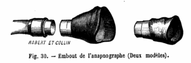
Mouthpiece and Nasal Mask, 1873. A mouthpiece and nasal mask used with the Apnapographe, a writing spirometer developed by Bergeon. From “Arsenal du diagnostic médical: recherches sur les thermomètres, les balances, les instruments d’exploration des organes respiratoires, de l’appareil cardio-vasculaire, du système nerveux, les spéculums uteri et les laryngoscopes” by Maurice Jeannel, published by Balliere, 1873, page 102.
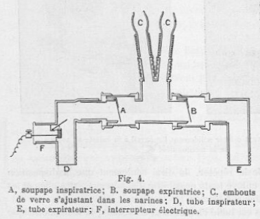
Nasal breathing Valve, 1904. Designed by Tissot. Used one-way valves so exhaled air could be collected and analyzed. Included an electical switch that was activated during inspiration. From J. Tissot, “Nouvelle méthode de mesure et d’inscription du débit et des mouvements respiratoires de l’homme et des animaux”, Journal de physiologie et de pathologie générale, 1904, vol 6, pp. 690.
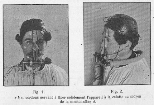
Nasal Breathing Valve, 1904. Designed by Tissot. Held in place by a headpiece. From J. Tissot, “Nouvelle méthode de mesure et d’inscription du débit et des mouvements respiratoires de l’homme et des animaux”, Journal de physiologie et de pathologie générale, 1904, vol 6, pp. 689.
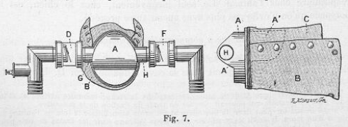
Tissot Valve with animal mask, 1904. Used one-way valves so exhaled air could be collected and analyzed. From J. Tissot, “Nouvelle méthode de mesure et d’inscription du débit et des mouvements respiratoires de l’homme et des animaux”, Journal de physiologie et de pathologie générale, 1904, vol 6, pp. 691.
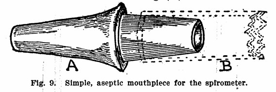
Mouthpiece, 1908. From, The Year Book of General Medicine, Volume 1, Year Book Publishers, 1908, page 90.
“A simple aseptic mouthpiece for the spirometer is described by Thomas A. Storrey. This mouthpiece (A) is made of wood, beveled on one end to fit easily between the lips. The other end is made to fit snugly in the bore of the rubber tubing (B) which leads to the spirometer. These may be made anywhere. The Narragansett Machine Company of Providence, R.I., has furnished me with tips at the rate of $3 per thousand. Each mouthpiece is used but once. It is then thrown away. At one-third of a cent each this is not extravagant. With such tips in use the danger of spreading contagion from mouth-to-mouth in our anthropometric investigations would disappear. (Fig. 9)”
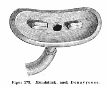
Denayrouse Mouthpiece, 1913. Physiologische Übungen und Demonstrationen: für Studierende By Robert Tigerstedt. Published by Taylor & Francis , 1913. Page 185.
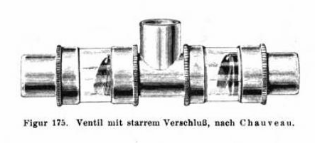
Chauveau Breathing Valve, 1913. Physiologische Übungen und Demonstrationen: für Studierende By Robert Tigerstedt. Published by Taylor & Francis , 1913. Page 186.
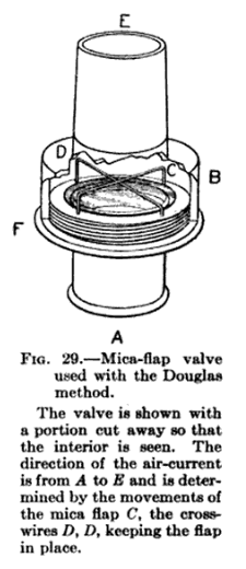
Mica Flap Valve, 1915. From Carnegie Institution of Washington Publication, Issue 216, Comparisons of Respiratory Exchange, 1915, page 68.
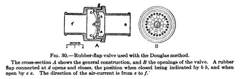
Rubber Flap Valve, 1915. From Carnegie Institution of Washington Publication, Issue 216, Comparisons of Respiratory Exchange, 1915, page 68.
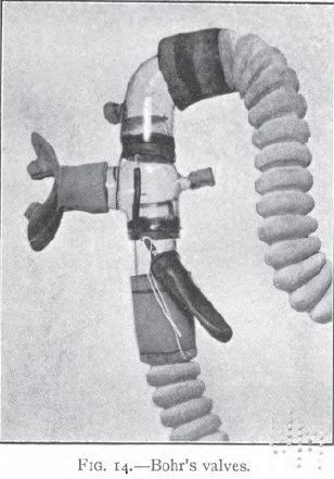
Bohr’s Valves, 1916. From: The respiratory exchange of animals and man by August Krogh, 1916, page 40.
“Valves such as Muller’s and other fluid valves, generally filled with water or mercury, were formerly used extensively. They have the advantage that leakage backwards is impossible, but their resistance is generally considerable. Zentz uses the “Darmventile” invented by Speck. These are certainly effective and the resistance very slight, but the valves are large and cumbrous. Reliable metal valves with a minimum resistance have been constructed by Chauveau (Tissot, 1904) and by the firm Siebe, Gorman (Douglas, 1911). Bohr constructed rubber valves which, slightly modified, have given entire satisfaction in Danish laboratories (fig. 14).”
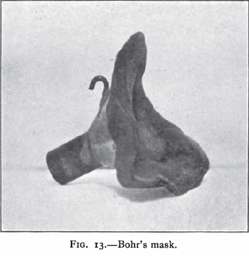
Bohr’s Mask, 1916. From: The respiratory exchange of animals and man by August Krogh, 1916, page 40.
“Masks of rubber which can be fitted on the face and enclose the mouth and nose are far more convenient than mouthpieces, but it is extremely difficult to avoid leakage. Bohr constructed masks which were specially fitted to each person on whom it was intended to experiment. These masks (fig. 13) consist of a funnel-shaped piece of tinplate coated on the edge with a substance used by dentists and know commercially as Stent’s composition. This substance becomes soft at a temperature of about 50 degrees, and can then easily be moulded on the face of a person and can be made to fit absolutely airtight when greased with lanolin, causing at the same time a minimum of inconvenience. These masks are much used in Danish laboratories for all experiments which have to last more than a few minutes at a time.”
One-way valve assembly, 1918. From: Yandell Henderson, AND INDIRECT CALORIMETRY VI. THE RESPIRATORY EXCHANGE APPLICATIONS OF GAS ANALYSIS: ARTICLE: J. Biol. Chem. 1918, 33:47-53.
“A form of valve which has proved convenient has recently been devised at the University of Minnesota by professors A.D. Hirschfelder and E.D. Brown. By their kind permission a diagram of two of these valves arranged for inspiration and expiration on a T-tube is shown in Fig. 2. Each valve is made of a large tin salve box with a disk of sheet rubber inside, held in place by a ring spring wire soldered to the box at one point. The crack around the box is made tight with adhesive plaster. In the figure the cover of one valve is removed to show the rubber and wire.”

Nose clip, mask and mouthpiece, 1920. From: The Newer Methods of Blood and Urine Chemistry, by By Rutherford Birchard Hayes Gradwohl, Abraham Jacob Blaivas, 1920, Page 369.
“The mouthpiece is made of soft pure gum rubber, and consists of an elliptical rubber flange having a hole in the center 2 cm. in diameter, to which on one side a short rubber tube is attached. On the opposite of the hole, at right angles to the rubber flange, are attached two rubber lugs. The rubber flange is placed between the lips, and the lugs are held by the teeth. The rubber tube of the mouthpiece is connected to the tube carrying the valves. The nose must be tightly closed if mouth breathing is used. This is accomplished by a nose clip, which consists of a V-shaped metal spring, the ends of which are provided with felt pads. A toothed ratchet is attached to the ends of the spring, and serves to hold the spring tightly clamped on the nostrils in the proper position.”
“Some individuals experience great distress when made to breathe through the mouth. For these it is best to use a face mask. Unfortunately at the present time no mask is entirely satisfactory. Perhaps the best is sold by Siebe, Gorman & Co. which is pictured in the cut. After being placed in position the face mask should be tested for leaks, which can be done by putting soap around the edges.”
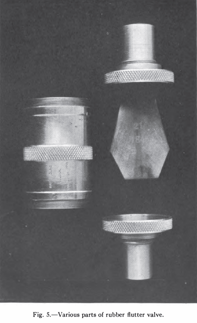 Rubber Flutter Valve, 1920. From: Laboratory Manual of the Technic of Basal Metabolic Rate Determinations, Walter Meredith Boothby, Irene Sandiford, published 1920 W.B. Saunders. Page 43
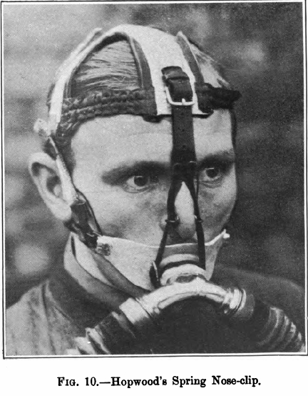
Nose Clip, Hopwood’s, 1920. Hopwood’s nose clip used in testing mine safety equipment. From The Department of Scientific and Industrial Research, Advisory Council, Second Report of the Mine Rescue Apparatus Committee, Published by His Majesty’s Stationary Office, 1920, page 34.
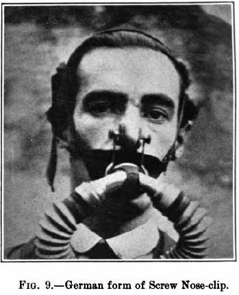
Nose Clip, German, 1920. A German nose clip used in testing mine safety equipment. From The Department of Scientific and Industrial Research, Advisory Council, Second Report of the Mine Rescue Apparatus Committee, Published by His Majesty’s Stationary Office, 1920, page 34.
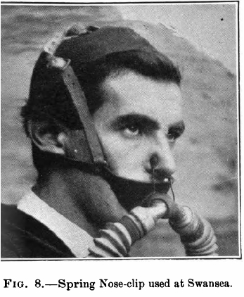
Nose Clip, Swansea, 1920. A nose clip used in testing mine safety equipment. From The Department of Scientific and Industrial Research, Advisory Council, Second Report of the Mine Rescue Apparatus Committee, Published by His Majesty’s Stationary Office, 1920, page 34.
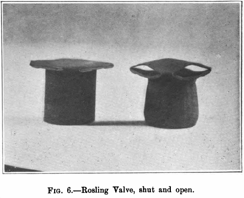
Valve, Rosling, 1920. A Rosling breathing valve. From The Department of Scientific and Industrial Research, Advisory Council, Second Report of the Mine Rescue Apparatus Committee, Published by His Majesty’s Stationary Office, 1920, page 31.
Valve, Split-Tube, 1920. A split-tube breathing valve. From The Department of Scientific and Industrial Research, Advisory Council, Second Report of the Mine Rescue Apparatus Committee, Published by His Majesty’s Stationary Office, 1920, page 31.
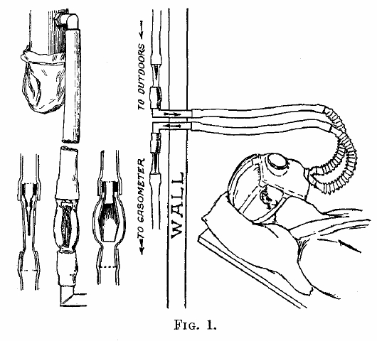
Mask, 1921. From: Notes on the apparatus used in determining the respiratory exchange in man: I. an adaptation of the French gas max for use in respiratory work, by Cameron Bailey, J. Biol Chem 1921; 47:277-279.
“The rubber gas mask used in the French army is admirably suited to this work. It is made of thick rubber, covers the whole face, and presents broad surfaces which closely engage the forehead, sides of the face, and jaw. The tissues in these regions are well supported by the bony framework of the face and the mask readily adapts itself to these fixed surfaces. It is held in place by elastic straps passing around the head. In emaciated subjects, leaks may occur above of below the zygoma, in the area the pull of the straps is in the same plane as the surface of the face. In such rare instances the leaks are overcome by placing 6 inch rubber sponges over these areas of the mask and binding them firmly in place with a 3 inch bandage. In this mask, the incoming air is directed upwards towards the windows, the opening of the expiratory tube being opposite the nose and mouth. In this way the space is perfectly ventilated and no discomfort results. Rubber flutter valves are eminently satisfactory for use with these masks. They are conveniently enclosed in flattened glass tubes introduced as near the mask as practicable. A satisfactory arrangement of mask valves for the Tissot method is shown in Fig. 1. The subject reclines in a wheel chair in the rest room, the tubes pass through the wall into the laboratory where the valves are mounted, the tubes then lead directly to the air supply and to the gasometer. A window permits the operator in the laboratory to observe the subject, while at the same time he can follow the respirations by watching the movement of the valve and start and stop the test by turning the 3-way valve on the gasometer.”

Tissot Valve, 1922. Valve design attributed to Dr. Tissot, first described in the Journal de Physiologie, 1911. From Basal Metabolism: Its determination and application. Frank Sanborn editor. Sanborn Company Publishers, 1922. Page 55.

Denayrouse Mouthpiece, 1922. From: Endocrinology and Metabolism. Llewellys Barker, MD, editor. Published 1922. Chapter: The normal process of energy metabolism, John R. Murlin. Page 532.

Rosling Valve, 1922. The Rosling valve was originally patented in England prior to World War I and was used in mining and gas masks. This drawing is from Cecil Rosling’s American patent application. The valve had low resistance and unlike many valves of the time, the rubber diaphragms themselves provided the spring action. The Rosling valve was used extensively in physiological research from the 1920′s to the 1950′s.
Benedict valve, 1922. From Boston Medical and Surgical Journal, 1922, v186, p460.
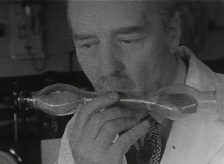
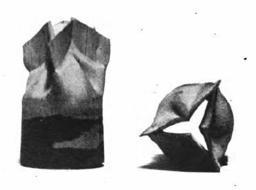
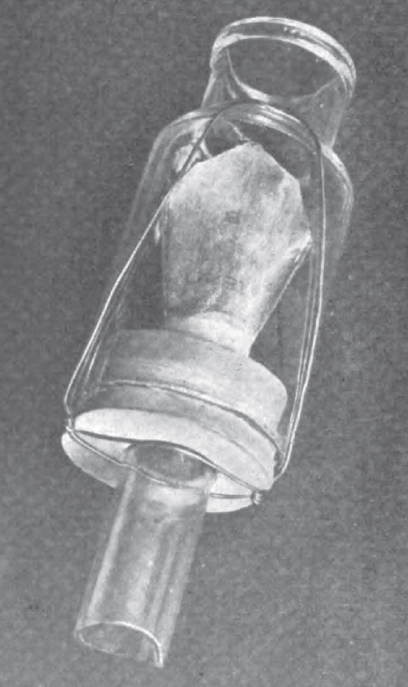
Flutter Valves, 1934. Found at Europeana.Eu. From an educational film entitled “Methods of measuring metabolism and basal metabolism Krogh and Douglas bag”, Produced by the Department of Physiology, Cambridge University, 1934.
A pair of flutter valves inside glass. Intended to be used to measure minute ventilation with a Douglas bag.
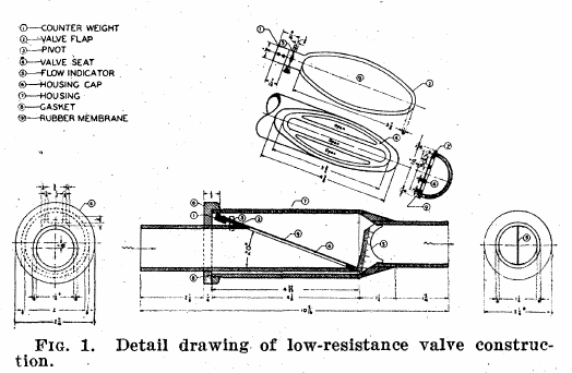
Low resistance valve, 1946. From: A low resistance valve and indicating flowmeter for respiratory measurements. By Leslie Silverman and Robert C. Lee. Science 1946; 103: p537.
“It can be noted that the valve flap angle is very low (20 degrees), and thus very little change in direction is necessary in permitting air to pass, once the valve begins to open. The area of the valve flap surface is large, and hence a low pressure will exert enough force to open it. The weight of the valve flap is offset by the counterweight. This counterweight (4 grams) was proportioned to give a low opening pressure and yet allow an adequate amount of of positional movement in the complete valve. The seating surface of the valve is limited to the small longitudinal braces and edges of the seat periphery. In order to reduce the adhesive effect of the rubber membrane when wet, the seating surfaces are dusted with talcum powder. This powder prevents the rubber membrane and Lucite seating surfaces from wetting and also helps preserve the membrane.”
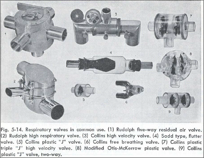
Breathing valves available in the USA in 1963. Attrributed to an article authored by Consolazio, Johnson and Pecora, title and journal unknown. From: page 40 of of a 2003 doctoral dissertion by Yaser Mahfouz Atwa Saad Elgohari.
Undated Collins publicity photo.
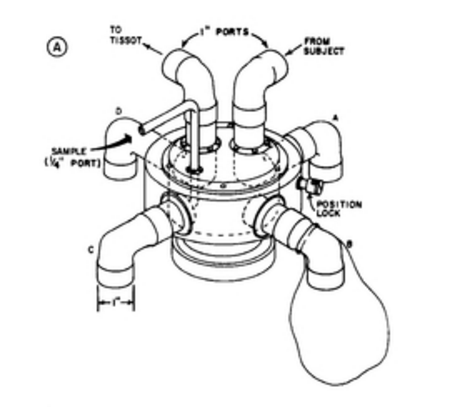
Armstrong-Mahler Valve, 1969. From Journal of Applied Physiology, 1969 27(5): page 765.
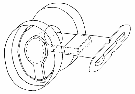
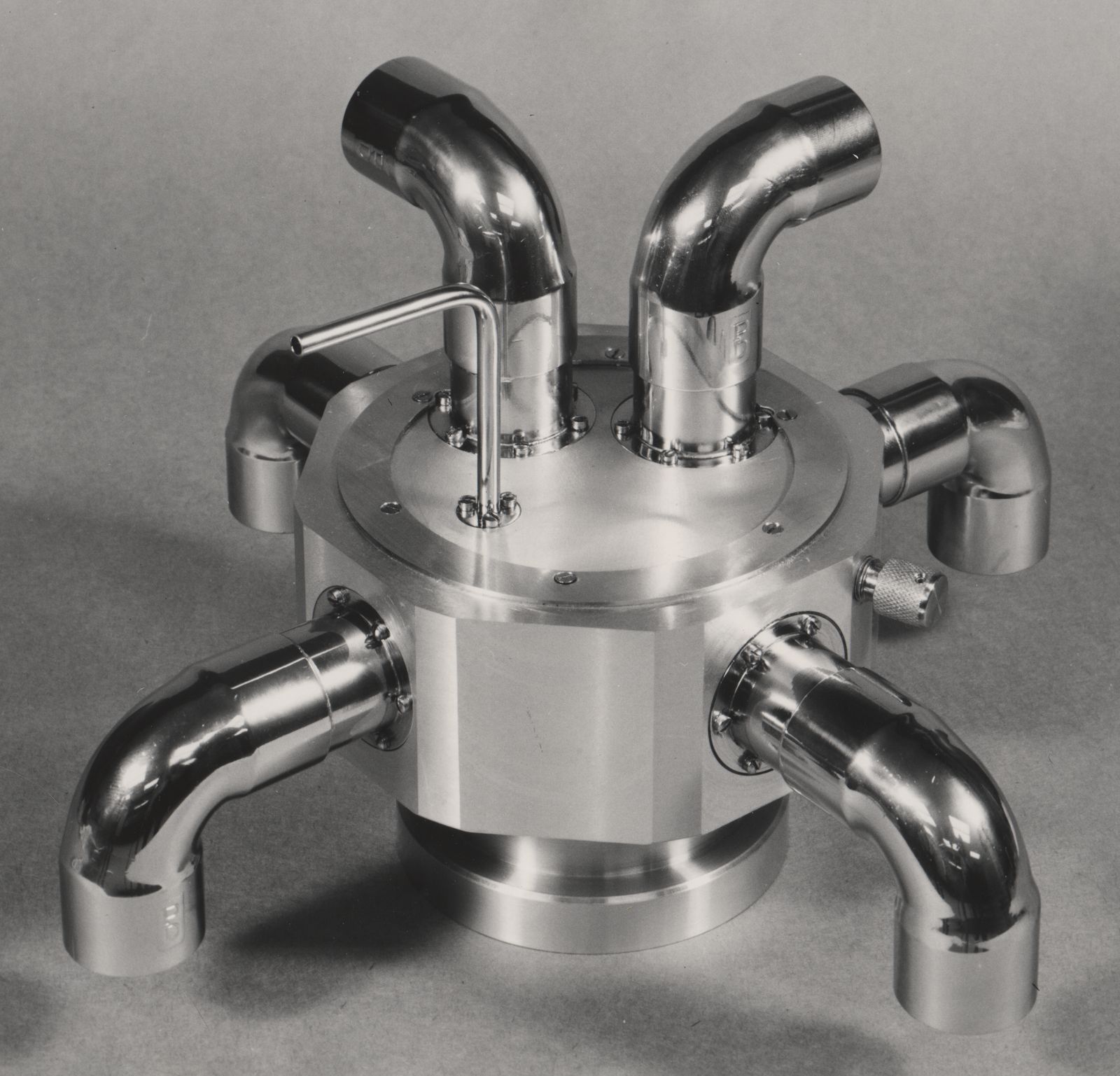
“O2 deficit and debt. A collection bag is connect to each outlet (A, B, C, D). Initially when the valve is in the position shown, exhaled gas flows from the mouthpiece and into the bag on the outlet which is in position A. When this collection period ends the outer rim is rotated so that outlet A is in position B, and an empty bag is in position A. When the next collection period begins a third empty bag is in position A, the second collection bag is in position B and the first bag is in position C and ready for sampling. When the fourth collection period begins the above sequence is repeated, and the first bag is rotated into position D and emptied into the Tissot. The first bag is ready to be refilled when turned
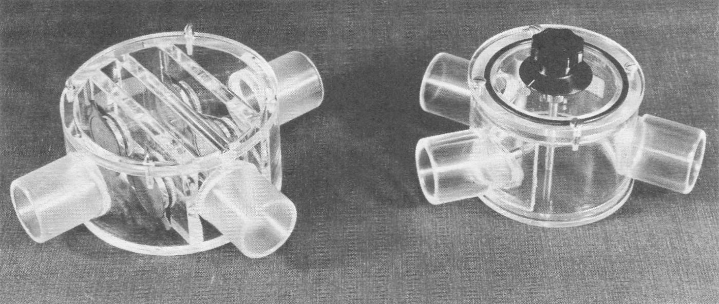
Collins Breathing Valves, 1972. From “Laboratory manual for physiology of exercise”, by Laurence E. Morehours, Published by C.V. Mosby, 1972, page 88.
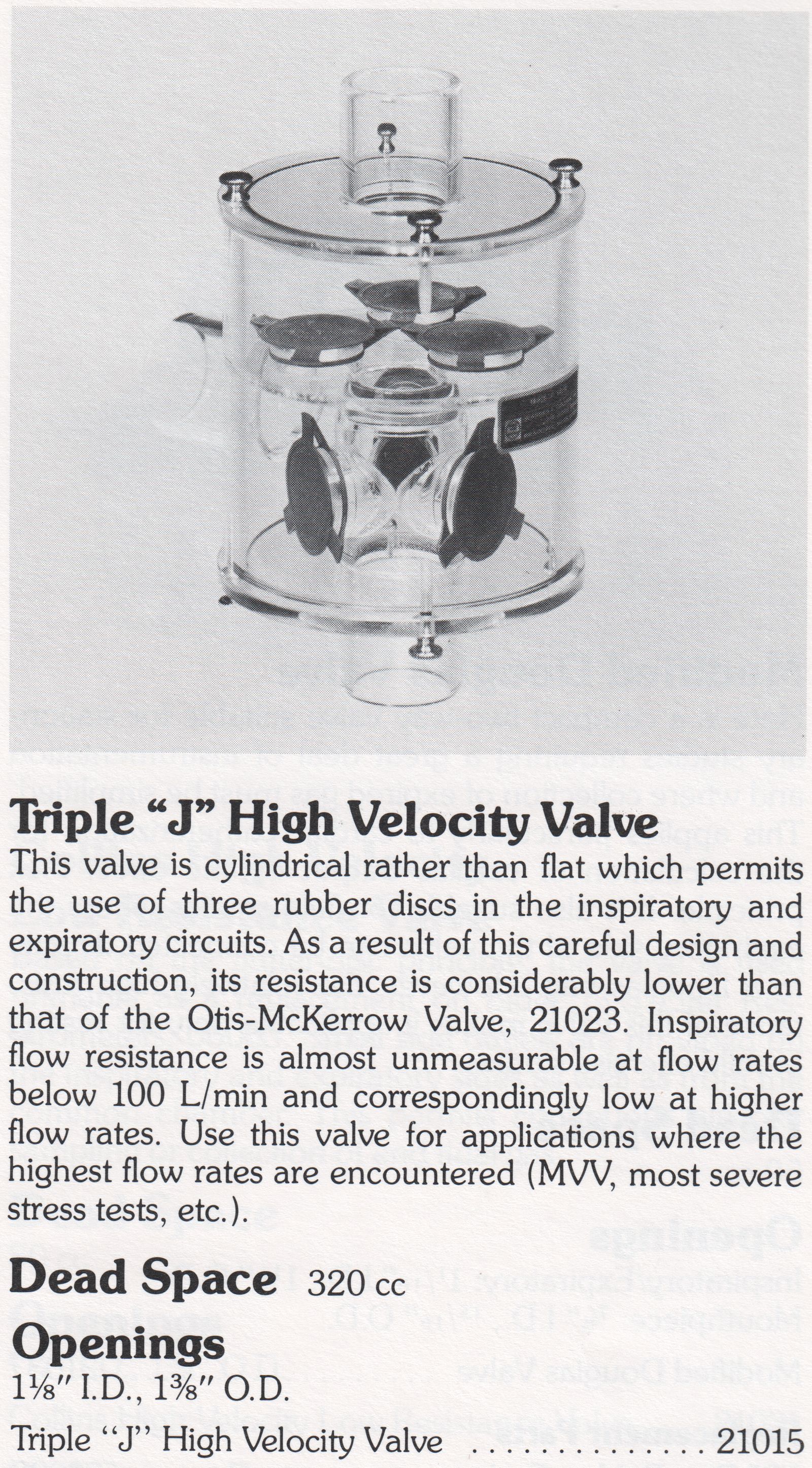
Collins Triple-J High-Velocity Valve, 1982. From the 1982 Collins Supply Catalog.
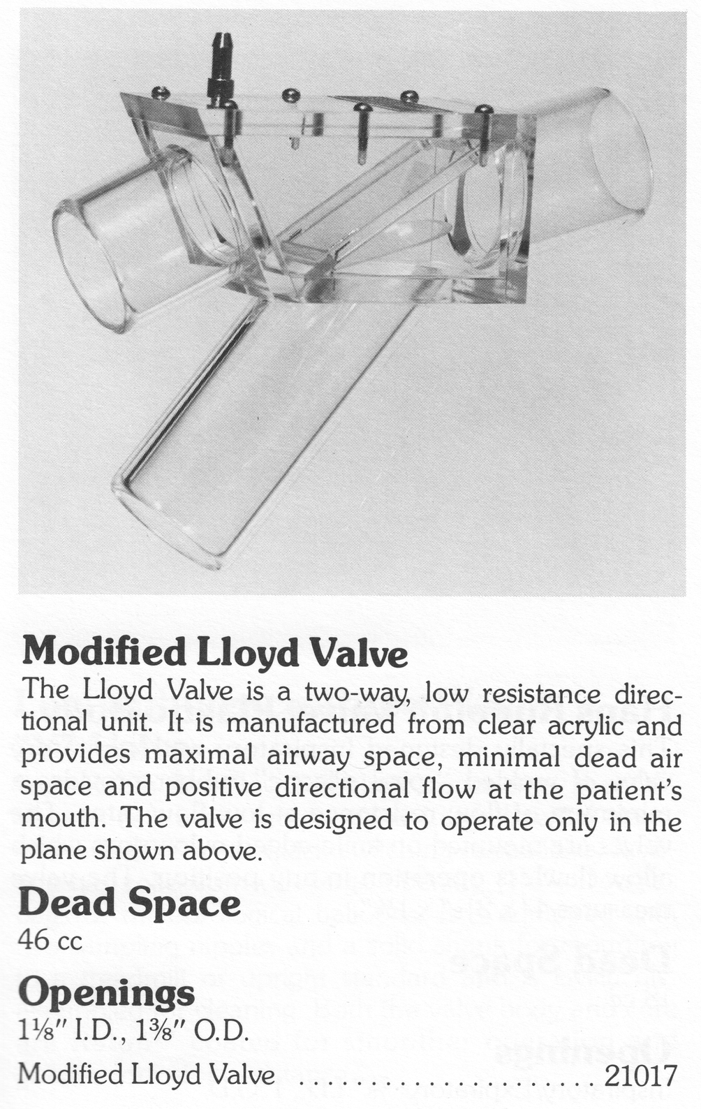
Collins Modified Lloyd Valve, 1982. From the 1982 Collins Supply Catalog.
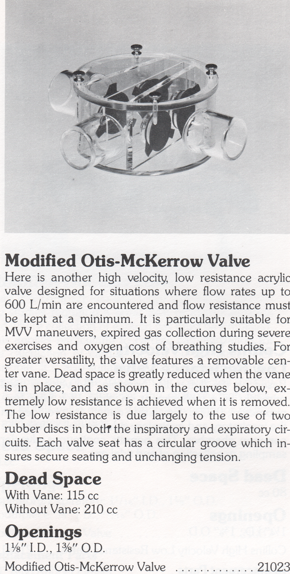
Collins Otis-McKerrow Valve, 1982. From the 1982 Collins Supply Catalog.
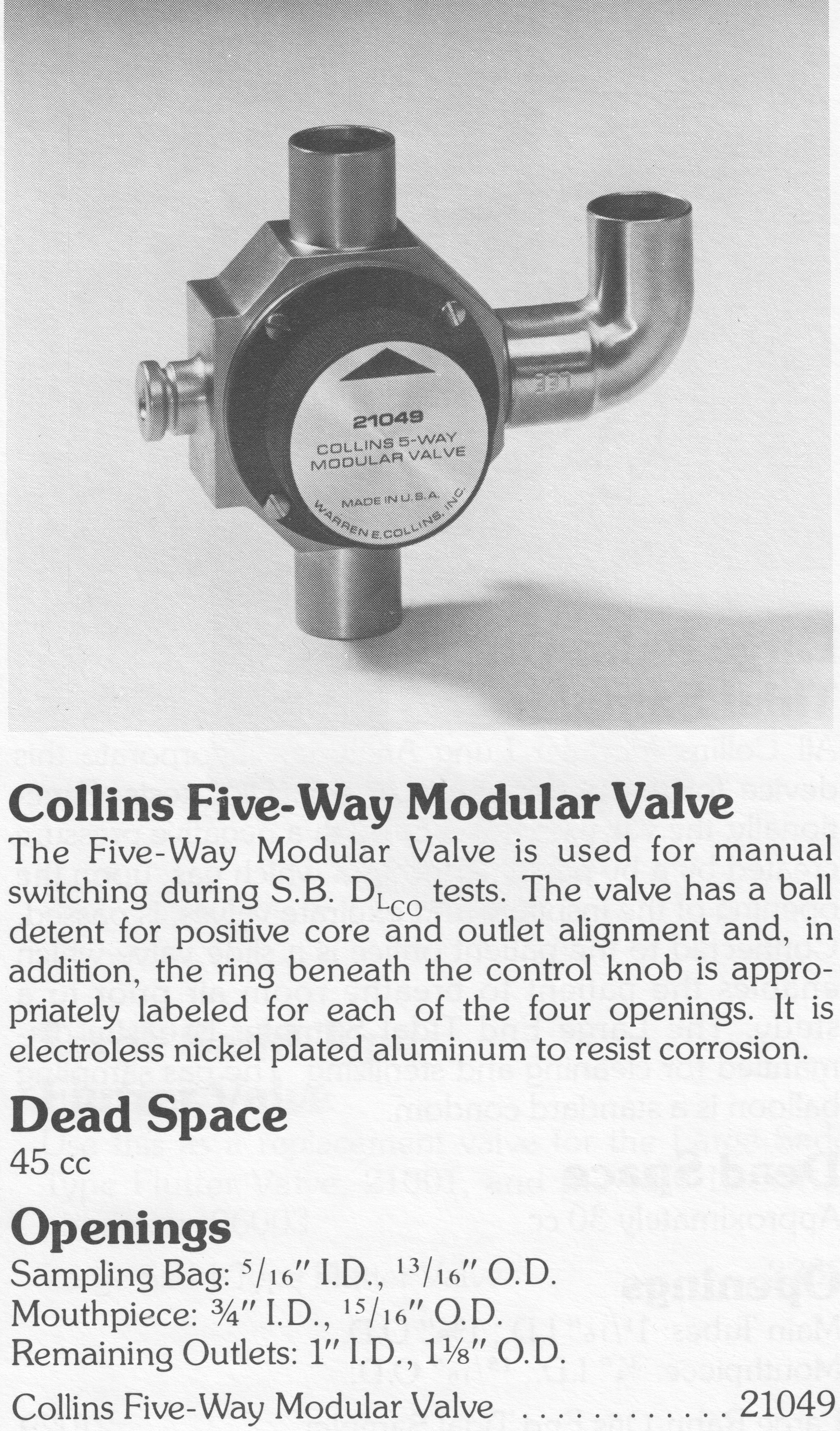
Collins 5-Way Valve for DLCO testing, 1982. Yes, at one time there were no automated single-breath DLCO systems. Unseen is the opening for the patient mouthpiece on the back of the valve. The opening on the left was for the rubber alveolar sample bag. From the 1982 Collins Supply Catalog.
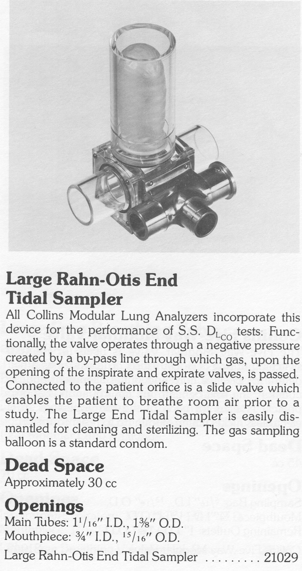
Collins Rahn-Otis End Tidal Sampler, 1982. An ingenious valve that used inspiratory and expiratory pressures to fill a small sampling balloon (yes, a condom) with end-tidal gas for steady-state DLCO tests. Valve is pictured upside down. In use the sampling balloon extended below, not above, the mouthpiece. From the 1982 Collins Supply Catalog.
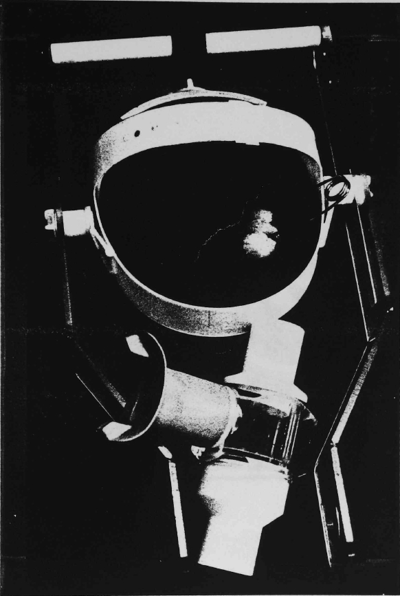
Mouthpiece and headset for exercise testing, 1986. From a doctoral thesis on the Maximal Acceptable Weight of Lift by J.E. Fernandes
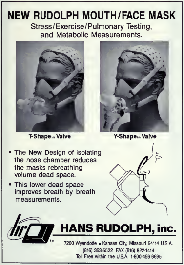
Mouth/Face Mask, Hans Rudolph, 1991. From Respiratory Care, 1991, Volume 36, No. 5, Page 437.

PFT History by Richard Johnston is licensed under a Creative Commons Attribution-NonCommercial 4.0 International License.