Category Archives: Carbon Dioxide

Spirometer, Goiffon, 1935

spirometer_goiffon_1935

A recording spirometer, attributed to Goiffon.  It appears to have been used to measure the hyperventilation from rebreathed air (response to CO2 test).  It recorded respiration on a strip of paper. From La Presse Medicale, 1935, no. 36, page 716.  Attributed to Goiffon, Parent et Waltz, Annals de Medicine, Mai et June 1934, “L’Insuflisance refelexe de la ventilation pulmonaire”.

Spirometers, Krogh and Tissot, 1932, System for measuring CO2 Response.

Spirometers_Tissot_Krogh_1932_CO2_Response

From Nederlands Tijdschrift voor Geneeskunde, May 21, 1932, page 2465. “Oorspronkelijke Stukken. Bewusteloosheir, schijndood en hun behandeling met de inademing van Koolzuur-Zurrstofmengsels” by Dr. G C E Burger and Dr. M H Tromp.

Diagram of a breathing system containing two Krogh spirometers (one with soda lime CO2 absorbant, one without) and a Tissot spirometer.  Designed to measure tidal and minute ventilation while breathing different levels of CO2 up to 10 percent.


Balance Chemograph, 1905

1905_Balance_Chemograph

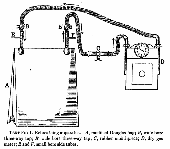
From: A balance-chemograph and the excretion of carbon dioxide during rest and work, by George Oswin Higley, University of Michigan PhD Dissertation, 1905, page 6.

Before the infrared absorption CO2 analyzer was invented CO2 was analyzed by being absorbed chemically and the change in weight measured.

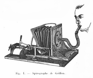
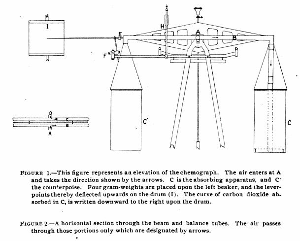
“The apparatus for absorbing carbon dioxide and recording on a blackened paper its rate of flow, is constructed as follows: (Fig. 1, Elevation). It consists of a Ruprecth lecture-room balance, capable of carrying a load of 6 kilograms in each pan and of turning to 5 milligrams. To the beam there was attached a copper tube one and one-hal centimeters in diameter as shown by figure 2. Dry air containing carbon dioxide, enters at A through a short piece of very thin rubber tubing made of a surgeon’s finger cot, passes through the portion designated by the arrows to the end of the beam and downward through two rubber connections like that just mentioned, and a glass tube D (Fig. 1) to the chamber for the absorption of carbon dioxide, upon the air of the balance. (C Fig 1.) From the absorption apparatus the air passes upward through similar connections to the balance-tube C, back on the opposite side of the balance-beam to the center, where it leaves the balance through another piece of rubber tubing, and then passes into guard tubes G’ and G”, which will be described later.

“Since there was a question of removing the carbon dioxide from air flowing at the rate of 30 liters per minute during work, the absorption apparatus is necessarily large. It consists of a beaker 20 centimeters deep, with cover of thin copper, provided with opening two centimeters in diameter, into which are fitted the inlet and outlet tubes. The air passes downward into the beaker through a thin glass tube 2 centimeters in diameter, to within about 2 centimeter of the bottom of the beaker, ending in a open space 3 centimeters deep and of a diameter equal to that of the beaker. (This open space was left because it was thought that the carbonic acid gas would thereby be more uniformly distributed throughout the whole cross-section of absorbent placed above.) The air now rises through the 5 kilograms of coarse, carefully screened soda-lime, and then through glass-wool covered with phosphorus pentoxide to hold back dust and the last trace of water formed in the reaction. This beaker when charged weighs about 5-1/2 kilograms. It is counterpoised by another beaker of the same exterior volume filled with spent soda-lime.”

Douglas Bag, Rebreathing system for CO2 response, 1925

Douglas_Bag_Rebreathing_CO2_1925

From: The respiratory response to carbon dioxide. By HW Davies, GR Brow, CAL Binger. Journal of Experimental Medicine, 1925, page 38.

“The effect of gradually increasing percentages of carbon dioxide was studied by means of rebreathing in a closed circuit consisting of a modified Douglas Bag with inflow and outflow tubes, a dry meter, and a rubber mouthpiece fitted with inspiratory and expiratory valves. The general arrangement of the apparatus is shown semidiagrammatically in text-fig. 1. The direction of airflow is indicated by means of arrows. A is the modified Douglas Bag of 100 liters capacity.  B, B’ are wide bored three-way taps. C is the mouthpiece. D is a twenty-light capacity “B-type” dry meter manufactured by D. MacDonald and company of Albany. The resistance of this meter is almost negligible even at the maximal rates of pulmonary ventilation produced by high percentages of carbon dioxide in the inspired air. E is a small bore side tube connected with an oxygen tank fitted with reducing valve and a flow meter calibrated with approximate accuracy rates of flow of less than 1 liter per minute. A similar side tube, F, is used to obtain samples of inspired air, either into exhausted sampling tubes or directly into the burette of the Haldane gas analysis apparatus. By way of the three-way stop cocks B,B’ the subject may be made to inhale from and exhale into the room air through the meter, and his normal respiratory rate and minute volume may be determined. When the stop-cocks are turned the apparatus becomes a closed circuit, inspiration and expiration being from and to the Douglas Bag, A.”