Spirometer designs evolved all through the late 1800’s. Many different ways of measuring air flow and volume were tried. Many designs fell by the wayside, but some techniques are still in use today.
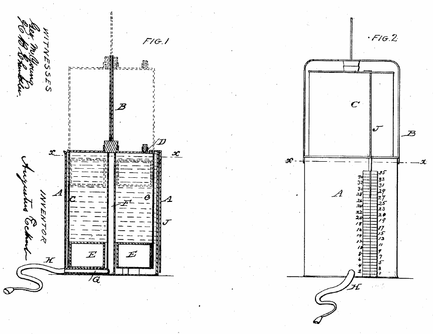
Eckert’s Spirometer, 1860. US Patent 26754 by Augustus Eckert of Dayton, Ohio. 1860. A non counter-weighted water-seal spirometer. Two of the patentable features were a guide rod (B) to keep the inner bell straight and an air-filled water-tight chamber in the rim of the bottom of the inner bell (buoy, E) that served the same purpose as a counter-weight. The cork (D) was removed after a vital capacity effort had been made and recorded to allow the bell to be returned to its lower position. There is no evidence this spirometer was ever manufactured.

Coxeter’s spirometer from 1861. “This instrument differs from Hutchinson’s in principal, and possesses the advantage of equal accuracy, great portability and comparative cheapness. It consists of two bags, one acting as a reservoir for expired air, and the other as a measure. The air is first expired into the larger back supplied with stopcocks to retain it. The next step is to pass seriatim the air into the measure bag, and to calculate the amount. The second bag can contain from 40 to 50 cubic inches, and it is to be filled from time to time, till the whole amount is measured. This instrument only costs 26s., and Mr. Coxeter I understand, has very recently improved it.”From: The physical examination of the chest in pulmonary consumption and its intercurrent diseases by Somerville Scott Alison. 1861. Page 351.
Mitchell’s Spirometer, 1863. “A spirometer, made upon the plan of a dry gas meter, has been for some time employed in Germany, and was introduced into use by Dr. W. Weir Mitchell. It is altogether more simple in its management than the rather clumsy instrument of Hutchinson, and affords fully as accurate results.” From: A Treatise on hygiene. By William Alexander Hammond, 1863, page 42.

Weiss Spirometer, 1863. “Weiss’ modification of Hutchinson’s spirometer. There is less mechanical friction in this instrument than in the original one, owing to the substitution of one large pulley for two small ones.” From: A Catalogue of Surgical Instruments, Apparatus, Appliances, Etc, John Weiss, 1863, plate XLII.
Salter Spirograph, 1865. From: Lectures on Dyspnea, Lecture III. By Hyde Salter, MD. The Lancet London: A Journal of British and Foreign Medicine, Surgery, Obstetrics, Physiology, Chemistry, Pharmacology, Public Health and News, Volume 2, October 28, 1865, page 475. Contained two spirometers; a set of valves and levers caused each to be emptied and refilled in opposition to the other. It included a kymograph.
Dr. Dio Lewis’ Spirometer, 1865. Invented by Dr. Dio Lewis who advocated health through exercise. From: Weak lungs and how to make them strong. By Dr. Dio Lewis, 1865. Page 259.
A description of the spirometer’s mechanism comes from Dr. Charles L. Ives who wrote in the Proceedings of the Connecticut Medical Society, 1867 issue, page 192:
“In like manner, to expand the lung by means of its contained air the spirometer of Dr. Dio Lewis proves of very great service. In this instrument, the air is blown into a very small elastic chamber, which, by its expansion, forces apart a spiral spring, whose movements are registered on a dial. As the air cannot escape from the small chamber the reaction on the lungs is equal to the force with which it is blown in. A degree of the dial is stated to mark a pressure of an ounce to the square inch, and when the pressure is raised, as with gradual practice it may be safely to four or five lbs. to the inch, a power is exerted that will the possibility of any air-vesicles remaining unexpanded, in which the epithelial debris may find lodgement.”
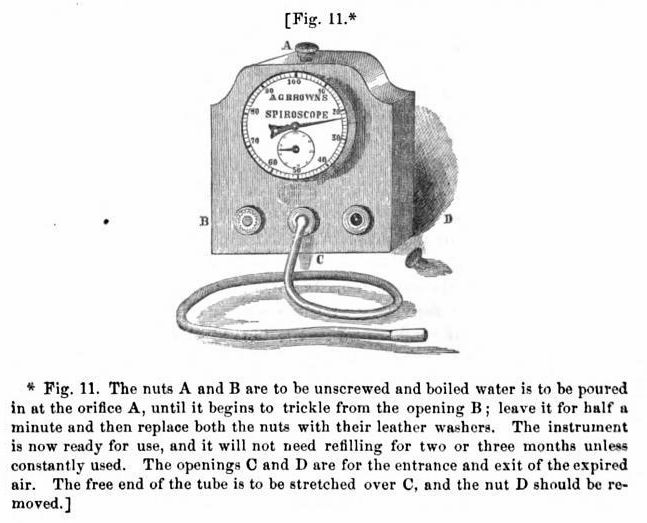
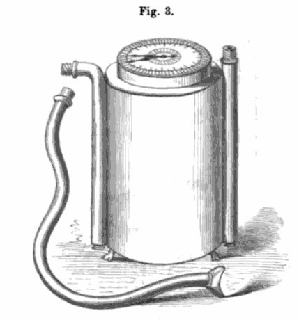
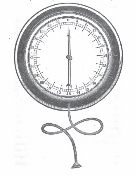
Brown’s Spiroscope, 1866. ”Mr. A. Gardiner Brown’s spiroscope is a new and efficient instrument for ascertaining the breathing capacity. It is a wet meter, 6-1/2 inches square, having a dial with two registers, revolving from left to right, marking in a complete revolution 100 and 1000 cubic inches respectively, and a few feet of vulcanized India-rubber tubing to breathe through. Its advantages are facility of management, compactness, portability, security of contained fluid and it may be used several times by the same person without readjustment. The air is measured at its initial temperature. The patient should be taught to practice a powerful inhalation, and as complete an expiration as possible, before noting the mean numbers registered in several trials. It should be placed at a convenient height for a person sitting or standing.” From: The Science and practice of medicine, Volume 2, by William Aitken, 1866, page 553.
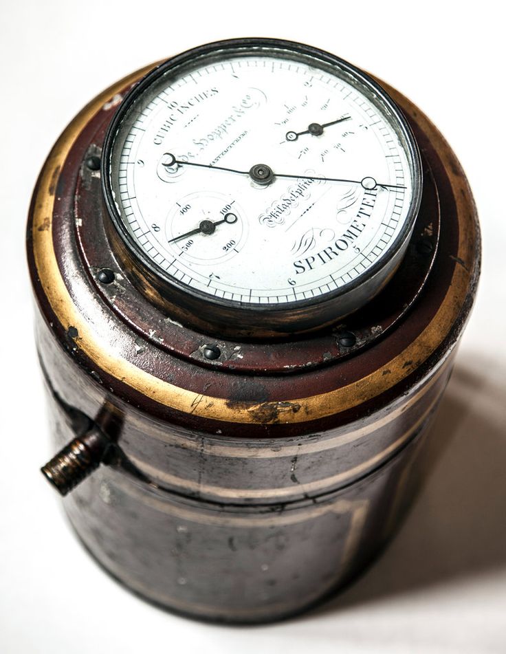
Code, Hopper and Co. Spirometer, late 1860’s. Found on GalleryGoGoPix, and originally posted on Pinterest where it was attributed to a New York Times article on the Mutter Museum. Based on a gas meter design and manufactured in Philadelphia, this spirometer was used in a large study of post-Civil War soldiers.
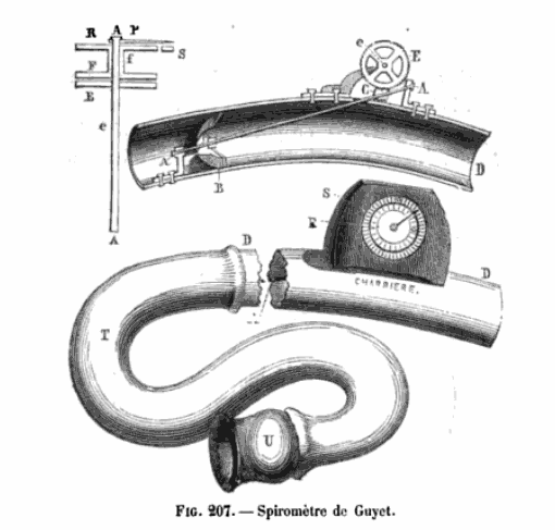
Guyet’s Spirometer, 1869. A small turbine or fan was turned by airflow which drove a small set of clockwork gears attached to a dial. The curve in the tube is so that the rod that connected the fan to the gears could be straight and yet the gear mechanism could remain outside the tube. From: Nouveaux éléments de pathologie générale, de séméiologie et de diagnostic. by Eugène Bouchut, 1875, page 865
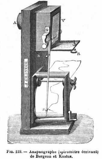
Apnapographe, 1868. From Traité élémentaire de physique médicale, Wilhelm Max Wundt, Armand Imbert. Published 1884, Paris. A description of its function, from Outlines of Physiology in Its Relations to Man, page 388, by John Gray McKendrick and James Macelhose, 1878 is as follows:
“A valve, or mobile plate of aluminum, V, forms one side of a rectangular box put into communication by A with a respiratory tube terminated by a mouth or nose-piece. The axis of rotation of the valve carries a very light lever, S, which writes on a strip of paper moved by clockwork. If air be propelled through the tube into A with each movement of inspiration and expiration, the variations of the pressure of the air in the air passages are transmitted to the valve which, by the lever, inscribes on the paper. The instrument has been graduated so as to suit bands of paper divided into small squares, each square representing a certain amount of air. Thus the instrument registers not only the pressure of the air, but the quantity inspired and expired, and the rapidity of the current of air. With such instruments, it may be shown that when the lungs have been emptied by as much as possible of air by the most powerful expiratory effort, they still contain a quantity over which we have no control, and which may be estimated at about 100 cubic inches. This has been termed residual air. In addition to this residual air, there are about 100 cubic inches constituting supplemental air, or the air that remains in the chest after an ordinary expiration, in addition to the residual air already mentioned. This there are about 200 cubic inches of air in the lung after a gentle expiration. If then, inspiration takes place gently, from 25 to 30 cubic inches are introduced; these, constituting tidal air, are expelled with the next expiration. We find, therefore, that in ordinary respiration there are 200 cubic inches of air in the lungs, and an inward and outward current of say 30 cubic inches; but, finally, it is possible by a very deep and prolonged inspiration, to introduce 100 cubic inches more. This last quantity is called complemental air. After the deepest inspiration there are, therefore, in the lungs 330 cubic inches of air, which number expresses the maximum capacity of the lung.”

Brown’s Spirometer, 1870 Advertisement. A non-counterweighted, water-seal spirometer with a rectangular bell. From: The Medical Gazette: A Weekly Review of the Medical Sciences, Volume 5, edited by H.W. Turner, 1870, page 134.
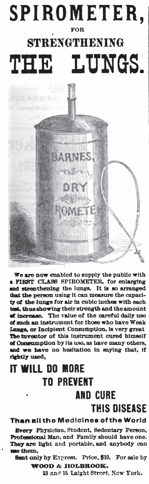
Barnes Spirometer, 1875 Advertisement. A description from The Science and practice of Medicine, Volume 2, 1866, By William Aitken, page 563: “The Lung Tester of A.P. Barnes (to be had of Messrs. Codman & Shurtleff, Boston) is the simplest and cheapest of all spirometric instruments. It consists of a cylindrical bag of India-rubber cloth, closed at each extremity by a disk of wood, and furnished with two metallic tubes; one tube enters laterally at the bottom, and is about three inches long; the other, vertical, is about twelve inches long, and graduated, and inserted in the centre of the upper disk. A flexible tube of proper length, with a mouthpiece is stretched over the outer aperture of the lower metal tube, and through this a forced expiration is made; the expired air fills, more or less, the bag and the vital capacity is recorded on the upper tube, which is forced up as the bag expands. The bag is enclosed in a tin cylinder, shut at both ends with two holes for the tubes.” From The Herald of Health, 1875, January issue, page 93.
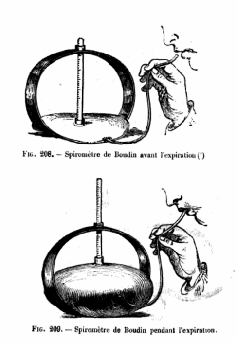
Boudin Spirometer, 1875. From: Nouveaux éléments de pathologie générale, de séméiologie et de diagnostic. by Eugène Bouchut, 1875, page 866.
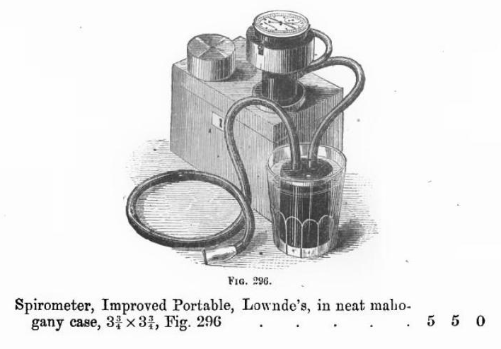
Lowne’s Spirometer, 1876. The actual mechanism is unknown but it was likely a turbine or fan. From: A Catalogue of Surgical Instruments, Arnold and Sons, 1876, page 121.
Lecuyer Spirometer, 1876. Made by Walter Lecuyer, Paris, of iron and brass construction. from http://www.sciencemuseum.org.uk/images/I019/10284273.aspx

Burt’s Spirometer, 1876. Drawing is from Patent #180842, filed August 1876 by W.H Burt. This spirometer appears to have been manufactured and sold because it was reviewed by Eldridge C. Price, MD in the 1884 issue of Medical Times (Volume 12, page 40):
“Burt’s instrument requires a maximum amount of muscular strength, and in the haemmhorragic diathesis its use is dangerous. In fact the instrument is nothing but a modified manometer, and is no index of lung capacity. I have seen the worthlessness of this instrument as a spirometer illustrated, when a well-muscled man of 5 feet 7 inches of height, who at one sudden and powerful expiration forced the mercury above the 300 cubic inch index, a few grains even shooting out of the tube. This gentleman’s actual respiratory capacity by future accurate mensuration proved to be 248 cubic inches.”
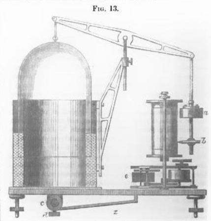
Gad’s Aeroplethysmograph, 1879. The first version of what came to be known as a Krogh spirometer. Described in a Physiology Textbook from 1899 as being used to measure the respiration in a rabbit. From Jacobsen, Pfluger’s Archive, 1888, page 236.
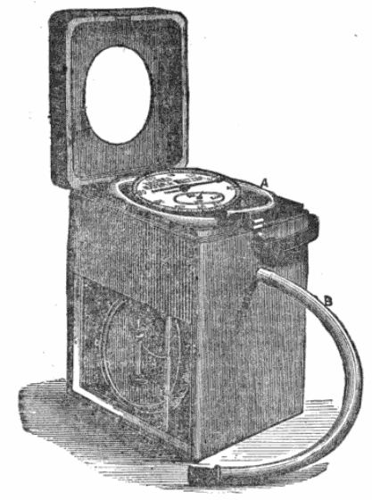
Jagielski Spirometer, 1879. From The London Medical Record, July 15, 1879, page 293.
”Dr. Jagielski’s Spirometer. This instrument is made by Messrs. Mayer and Meltzer, surgical instrument makers, 71 Great Portland St. W., and combines all the advantages of correctness, convenient size, simple management and neat appearance. It is cased in Morocco leather with a leather handle at the top, so that the instrument can easily be carried about. The height is 9 inches; width 5 inches; depth 6-3/4; its weight 5 pounds, 14 ounces. The instrument has three horizontal compartments, one above the other. The lowest compartment is open to view having two glass windows, and is divided by a vertical partition, on either side of which there is a round diaphragm, containing a space of 10 cubic inches each when expanded or filled; these two chambers can be seen working alternately during expiration and inspiration, the one contracting when the other expands. The middle horizontal compartment containing the valve apparatus communicating the movements from the lower compartment to the indicating apparatus above. This latter, or recording apparatus, has a visible dial, for which a cut is left open in the movable cover; around the dial there is an open space large enough to hold the elastic breathing tube.”
“This spirometer gives the vital capacity for inspiration as well as expiration, the amount of which may be read on the dial on which there are two hands to be seen in rotation when used. The large one indicates every single cubic inch in inspiration when moving from the left to the right, and, in expiration from right to left; once around it records 100 single cubic inches. The small handle on the small dial from 100 to 150, 200, 300 cubic inches on one rotation, and moves in an opposite direction to that of the large handle. In blowing into the tube it must be done with but a moderate strength, so that the large hand may move on slowly and steadily; that the observer may be able to follow its movements on the register.”
“These instruments, used for several years, show no difference in their accurate registration from the first day of use, and do not require any particular care when put away. Price six guineas each.”
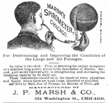
Marsh’s Spirometer, 1880. Advertisement from: The Medical Brief: A Monthly Journal of Scientific Medicine and Surgery, Volume 10, Issue 11, Page 26. Consisted of a rubber balloon with a measuring tape.
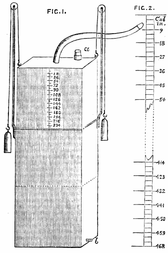
Rattray’s Spirometer, 1882. A counter-weighted, water-seal spirometer with a square bell. ”For stability and economy of space the cylinders are square; the inner of the thinnest – i.e. lightest – sheet zinc, 6 x 6 in. wide, 13 in. high and accurately counterpoised by weights of lead covered by brass or copper, hanging by 24 in. long silk or catgut cords over two pulley tipped 1/4 in. brass rods, 14 in. long, placed at opposite corners. The breathing tube, 1 in. in diameter and 28 in. long with an ebony or ivory mouth piece, should be attached to the center of the inner cylinder, either by a simple or screw attachment.” From Lancet, Dec 28 1882, page 915. A combined spirometer, aspiratory and aeroscope”, Alexander Rattray, MD.
From The Journal of the Royal Anthropological Society, 1891, Vol 20, page 29: “The spirometer exhibited was designed to register the number of cubic inches of air could expire at the resistance of a small constant pressure, the resistance of the instrument being equal to two inches of water pressure only. In the ordinary spirometer in use, formed of a counterbalanced receiver placed in a pneumatic trough, it is well known that according to the counterbalancing and difference of height of water in the receiver the resistance pressure may vary from -3 to +3 inches of water. In the first case, air may be drawn in during expiration from the nose. In the second the muscular power of the lungs will be enabled to expel nearly their entire contents. In another form of spirometer in which the expelled air moves light fans in air, it is found to be impossible from the unequal friction caused by corrosion and from leakage, to maintain nearly equal rates. The instrument before the meeting is constructed upon a principal common to the best forms of gas meters, but in this case the measurements being for small quantities, and needing no apparatus for continuous additions for registration, nor solidity of parts for rough handling the measuring apparatus is made much lighter and more delicate construction. It consists, as in the gas meter, of a light closed fan wheel, with cup fans, revolving nearly under water. The expelled air is projected into one side of the fan wheel. This side rises immediately by the minus gravity of the air to that of the surrounding water, while in the meantime another fan comes to position to receive the next quantity of expired air, and so on continuously so long as the lungs expire breath at a pressure beyond the small frictional resistance of the apparatus.
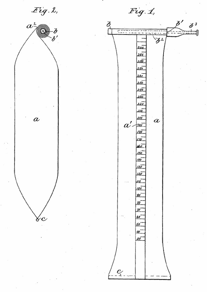
Barton’s Spirometer, 1888. From Patent number 392,711 by W.H.H. Barton.
“The instrument consists, essentially, of a flexible, collapsible, non-elastic reservoir or bag, preferably elongated or substantially cylindrical in shape, proved with a scale that indicates the cubic contents of the different portions of said bag when distended or filled.
“The bag or reservoir is provided at one end with a spindle or roll upon which the unfilled portion may be wound, so that the scale will indicate the cubic contents of the part of the reservoir that is filled. The said spindle or roll preferably forms the inlet to the reservoir and is provided with a suitable mouthpiece. One important advantage to this kind of spirometer arises from the fact that their is no back-pressure of the atmosphere, and the instrument is very light, compact and inexpensive.”
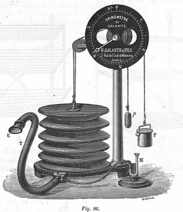
Galante Spirometer, 1891. A counter-weighted bellows spirometer. From Journal of surgical instruments, 1891, page 92. Found on the Medic Database. Image: med110220x1891x0088
Stanley Spirometer, 1891. From The Journal of the Royal Anthropological Society, 1891, Vol 20, page 29.
“The spirometer exhibited was designed to register the number of cubic inches of air could expire at the resistance of a small constant pressure, the resistance of the instrument being equal to two inches of water pressure only. In the ordinary spirometer in use, formed of a counterbalanced receiver placed in a pneumatic trough, it is well known that according to the counterbalancing and difference of height of water in the receiver the resistance pressure may vary from -3 to +3 inches of water. In the first case, air may be drawn in during expiration from the nose. In the second the muscular power of the lungs will be enabled to expel nearly their entire contents. In another form of spirometer in which the expelled air moves light fans in air, it is found to be impossible from the unequal friction caused by corrosion and from leakage, to maintain nearly equal rates. The instrument before the meeting is constructed upon a principal common to the best forms of gas meters, but in this case the measurements being for small quantities, and needing no apparatus for continuous additions for registration, nor solidity of parts for rough handling the measuring apparatus is made much lighter and more delicate construction. It consists, as in the gas meter, of a light closed fan wheel, with cup fans, revolving nearly under water. The expelled air is projected into one side of the fan wheel. This side rises immediately by the minus gravity of the air to that of the surrounding water, while in the meantime another fan comes to position to receive the next quantity of expired air, and so on continuously so long as the lungs expire breath at a pressure beyond the small frictional resistance of the apparatus.
“The registration mechanism consists of a light train of three watch wheels and a single balanced hand, which indicates the number of cubic inches on a dial. The hand stops and remains in its final position when the expired air no longer has the power to move the mechanism. The registration shows upon average about 10 percent more than that given in Dr. Hutchinson’s tables, which were taken from the register of an ordinary pneumatic trough spirometer.
“The hand is brought back to zero for another operation by pressing of a button, which is connected with simple mechanism adapted to this end.”
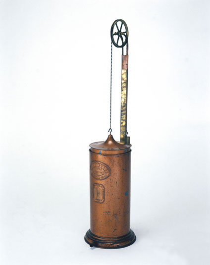
A G Spalding Spirometer, 1891. A Hutchinson-style spirometer with a dial read-out. Posted on Flickr by circasassy. Attributed to an A.G. Spalding & Bros. Gymnasium and Athletic catalogue from 1891. At a guess, the dial displayed the exhaled volume and was driven by the cables attached to the counter-weights that are likely hidden inside the side supports.
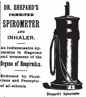
Shepard’s Spirometer, 1892. Combined an inhaler with a spirometer. From Homœopathic News: A Monthly Homœopathic Medical Journal, 1892, Volume 21, number 1, page 291.
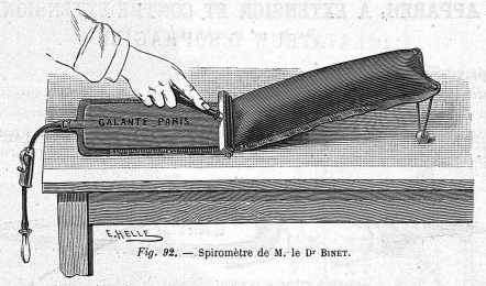
Binet’s Spirometer, 1892. A calibrated bag spirometer. From Revue des Instruments de Chirurgie, 1892, page 75. Found on the Medic Database. Image med110220x1892x0075.
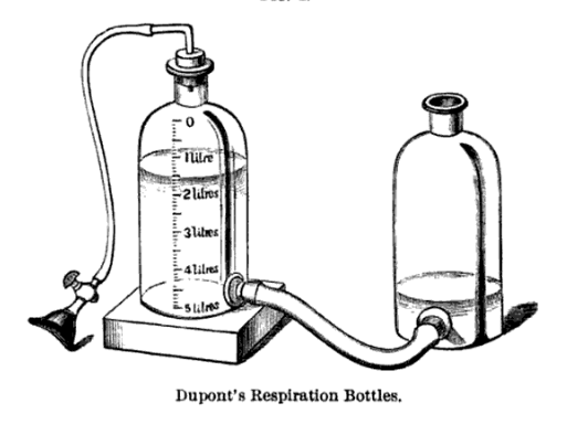
Dupont’s Spirometer, 1895. From ‘Physical and Natural Therapeutics: The Remedial Uses of Atmospheric Pressure, Climate, Heat and Cold, Hydrotherapeutic Measures, Mineral Waters, and Electricity’ by Georges Hayem, Lea, 1895, page 20.
“The open bottle is filled with water and then elevated so that the water flows into the second bottle up to the line marked zero. The stopcock is now closed, and the two bottles are placed on the same plane. The patient takes an inspiration and applies his mouth to the funnel, opens the stopcock, and expires into the bottle. At the end of the expiration the stopcock is again closed. When the two bottle are placed so that the water in them is at the same level, the amount that is thereby made to flow into the graduated bottle indicates the volume of expired air at the pressure of the atmosphere.”
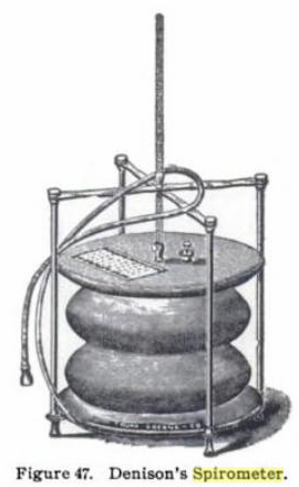
Denison’s Spirometer, 1899. A bellows spirometer. From: The Mechanics of Surgery: (1899) by Charles Truax, page 48.

PFT History by Richard Johnston is licensed under a Creative Commons Attribution-NonCommercial 4.0 International License.