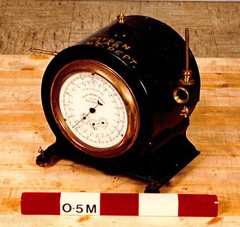
Gas meter type. Measurements: length 460 mm; width 410 mm; height 460 mm. Found on Science Museum Group Online Collections.
Gas meter type. Measurements: length 460 mm; width 410 mm; height 460 mm. Found on Science Museum Group Online Collections.
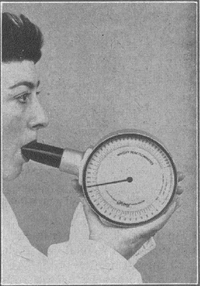
From: Wright, B. M., and C. B. McKerrow. “Maximum forced expiratory flow rate as a measure of ventilatory capacity.” British Medical Journal 1959; 2.5159, page 1043.
“The general appearance of the instrument, which weighs about 2 lb. (900 g.), and its method of use are shown in Fig. 2. The subject is asked to take a deep breath, as for a vital capacity, to place the mouthpiece in his mouth, and then to blow into the instrument as hard as he can. It is not necessary to try and empty the lungs, and it is undesirable to do so, because it is unpleasant and tiring, but a certain amount of “follow through” is required. After a couple of practice blows, three attempts in succession are recorded and the average is taken. This is statistically a more satisfactory procedure than simply taking the highest reading,although logically the latter would be preferable, since a maximum if being measured. Most subjects will give three readings with agree with 10% after the practice tries, but the observer must ensure that the subject is really trying his hardest. As with all ventilatory tests of this kind, including the M.V.V., failure to produce reasonably concordant results usually indicates a lack of co-operation.”
From: Wright, B. M., and C. B. McKerrow. “Maximum forced expiratory flow rate as a measure of ventilatory capacity.” British Medical Journal 1959; 2.5159, page 1043.
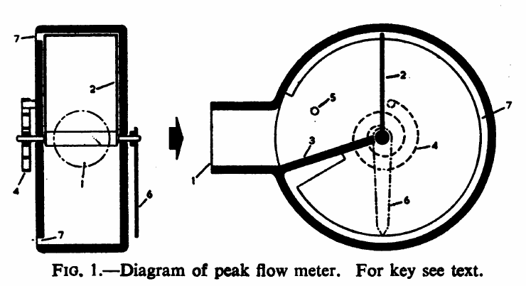
“The principle of operation of the instrument if illustrated diagrammatically in Fig. 1. A cylindrical cavity about 5 in. (12.7 cm) is diameter and 1 3/8 in. (3.6 cm) deep has a radial inlet nozzle (1), and contains a movable vane (2) pivoted in the centre of the cylinder and fitted closely without touching. A fixed partition (3) extends from one side of the inlet orifice to within a short distance of the boss of the vane, but again does not touch it. A spiral spring (4) attached to one end of the spindle of the vane tends to rotate it towards the inlet orifice, a stop (5) preventing it from passing the orifice. A pointer (6) on the other end of the spindle indicates the position of the vane on a dial (not shown) and also serves to counterbalance it. An annular orifice (7) extends from round the periphery of the cylinder at the back, from one side of the inlet orifice to the other.
“It can be seen that when air is blown into the instrument it cannot escape (except for a small amount which leaks past the vane_ until the van has moved and uncovered part of the annular orifice. When the aria of the orifice uncovered is such that the pressure behind the vane is just sufficient to balance the force of the spring the vane will come to rest in a position which will depend on the flow rate. Since for a given pressure the rate of flow is proportional to the area of the orifice, the deflection of the vane would be proportional to the air flow if the tension of the spring were constant. In practice, the tension of the spring increases with the deflection so the that deflection is proportionally less at high flows than at low. This has the effect of increasing the range of the instrument without loss of sensitivity at the lower end of the range, so that flows from 50 to 1,000 l./min can be covered in one instrument.
“The instrument is fitted with a ratchet which holds the vane and pointer in the position of maximum deflection. They can be returned to zero by pressing a release button.”
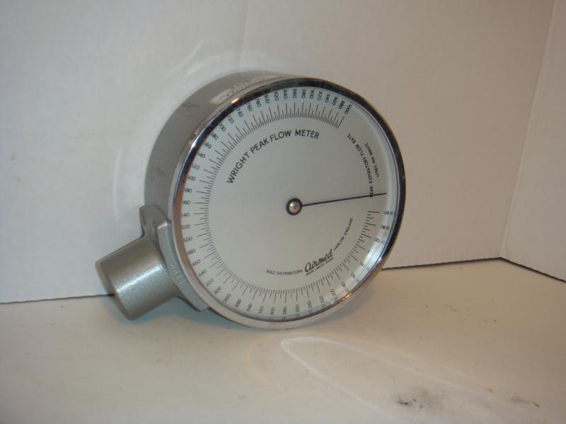
Wright Peak Flow Meter, circa 1970. From dgrespiratory.com