
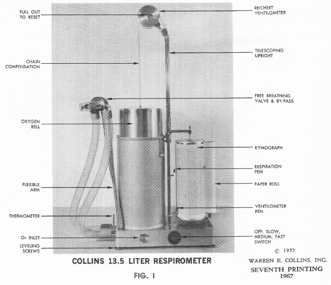
From Clinical Spirometry, Instructions for the use of the Collins Respirometer and for calculation and interpretation of data in pulmonary function and basal metabolism testing. Warren E. Collins, Inc. 1967.
From Clinical Spirometry, Instructions for the use of the Collins Respirometer and for calculation and interpretation of data in pulmonary function and basal metabolism testing. Warren E. Collins, Inc. 1967.
From Clinical Spirometry, Instructions for the use of the Collins Respirometer and for calculation and interpretation of data in pulmonary function and basal metabolism testing. Warren E. Collins, Inc. 1967.

Helium dilution circuit diagram for Collins Respirometers. From Clinical Spirometry, Instructions for the use of the Collins Respirometer and for calculation and interpretation of data in pulmonary function and basal metabolism testing. Warren E. Collins, Inc. 1967.
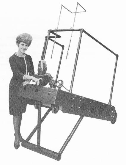
1-8 MPH treadmill for Stationary Exercise. From “Directions for operating a Collins chain-compensated gasometer”, Second Edition Cat. No. P-469. Warren E. Collins, Inc. May, 1967.
“This sturdy, yet easily portable, 1-8 MPH treadmill moves on 5” dia. ball-bearing casters. The optional “Electrolift” enables effortless inclination to 16 degrees (30%) with only the touch of a switch.”
From “Directions for operating a Collins chain-compensated gasometer”, Second Edition Cat. No. P-469. Warren E. Collins, Inc. May, 1967.

From “Directions for operating a Collins chain-compensated gasometer”, Second Edition Cat. No. P-469. Warren E. Collins, Inc. May, 1967.
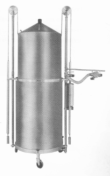
“PRINCIPLE OF CONSTRUCTION
“The Gasometer is made of stainless steel with an outer body and an inner body space about two inches apart to form a water seal for the Spirometer bell fo “float” in. The inner body is also shapes to occlude most of the dead space; and the whole unit is mobile on its own casters.
“CHAIN COMPENSATION
“When the Gasometer is filled with water to the petcock level, and the Spirometer bell is in its lowest position, the bells weighs less than when it is in its highest position, because of the buoyant effect of the water. To automatically compensate for this increasing weight so that the bell will be perfectly counterbalanced throughout its travel, the Collins Gasometer uses a chain to connect the bell to the main counterweight. Thus, as the bell rises, more segments of chain pass over the pulley. As the bell becomes heavier, so does the counterweight in direct proportion, with the result that almost perfect balance is achieved in all positions.
“ATTACHMENTS
“The Gasometer is fitted with the following standard attachments:
“Thermometer – indicates the temperature of the gas within the bell to facilitate various gas volume calculations.
“Auxillary Counterweight – removable so that the Spirometer maybe emptied quickly bu gravity.
“Two-Way Valve – permits addition or subtraction of gas while the patient is breathing. May also be used for sampling.”
Adjustable Height Knob – 120 Liter model: permits telescoping of the chain and pulley downwards. 350 and 600 liter models: pulley supports unscrew. Facilitates transportation and permits moving through low doorways.
“Leveling Screws – assures vertical position of the Spirometer so that the bell will not contact the side of the outer body.
Breathing Branch Assembly – supplies with the 120 liter Gasometer only. It serves as a support for the J-2 Valve or other breathing valves and tubing when the patient is to breathe directly into the Spirometer either from a sitting position or from the bedside.”

From Patent number 3,081, 766 granted March 19, 1963 to B. Dubsky et al. A combination of mechanical and electrical components. It was likely never manufactured.
“..it is an object of this invention to provide an open circuit spirometer for measuring both the quantities of air that are inhaled and exhaled by the subject or patient and the rates at which the air is inhaled and exhaled, without requiring the use of an air or oxygen container.
“Another object is to provide an open circuit spirometer that is constructed and arranged so that those parts with which the patient or subject comes into contactmay be conveniently and effectively sterilized.
“A further object is to provide an open circuit spirometer of relatively small size and weight so that it is conveniently portable and therefore may be used in laboratories and health centers, as well as at the bedsides of patients in a hospital.
“Still another object is to provide an open circuit spirometer in which the moving parts thereof have a negligible inertia, thereby to provide measurements of the respiration of a patient or subject with an increased accuracy.
“In accordance with an aspect of this invention, the foregoing objects are achieved by providing a spirometer comprising an open-ended conduit with a mouthpiece at one end through which the patient or subject inhales and exhales, two Pitot tubes disposed in the conduit and respectively opening axially toward the opposite ends or” the latter, a substantially closed chamber having a movable torsional body, a source of alternating current connected with the exciting winding so that torsional stressing of the body causes a signal voltage to be induced in the pick-up winding, and indicating or recording means connected to the pick-up winding so as to be actuated by the signal voltage.
“In a preferred embodiment of the invention, the signal voltage from the pick-up winding or coil is fed to an amplifier having a feed-back circuit and a non-linear resistor arranged so that the output from the amplifier is proportional to the square root of the input or signal voltage from the pick-up coil, and therefore proportional to the square root of the difference between the pressures sensed by both Pitot tubes which corresponds to the speed of movement of air through the conduit during inhalation or exhalation by the patient. Further, the output from the amplifier is fed to the control winding of a two-phase asynchronous servo-motor which suitably drives a carriage or movable support carrying a pencil or stylus engaging a strip or web of recording paper that is suitably displaced in the direction at right angles to the direction of movement of the carriage so that the position of the carriage, and hence of the stylus on the recording paper, is proportional to the quantity of air flowing through the conduit.”

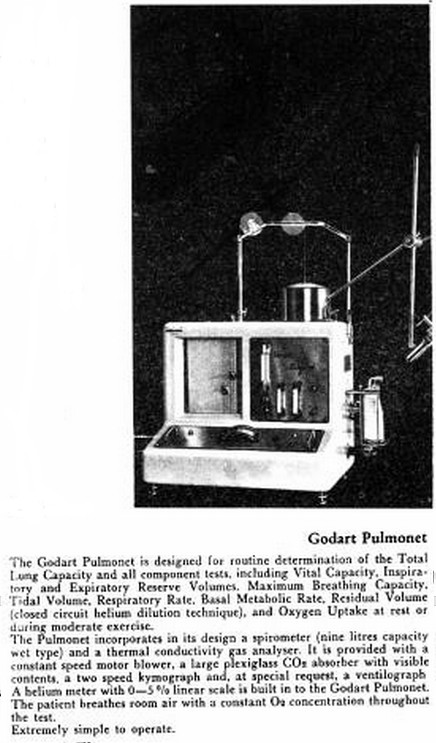
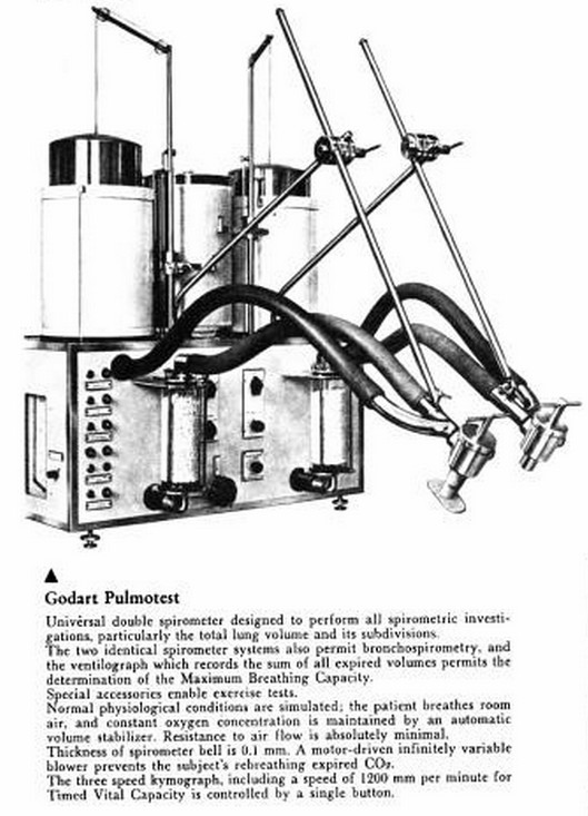
From Medical Electronic Laboratory Equipment 1967-68: Pergamon Electronics Data Series by G. W. A. Dummer, J. Mackenzie Robertson, published by Elsevier, page 581.
From Medical Electronic Laboratory Equipment 1967-68: Pergamon Electronics Data Series by G. W. A. Dummer, J. Mackenzie Robertson, published by Elsevier, page 578.
From Medical Electronic Laboratory Equipment 1967-68: Pergamon Electronics Data Series by G. W. A. Dummer, J. Mackenzie Robertson, published by Elsevier, page 578.