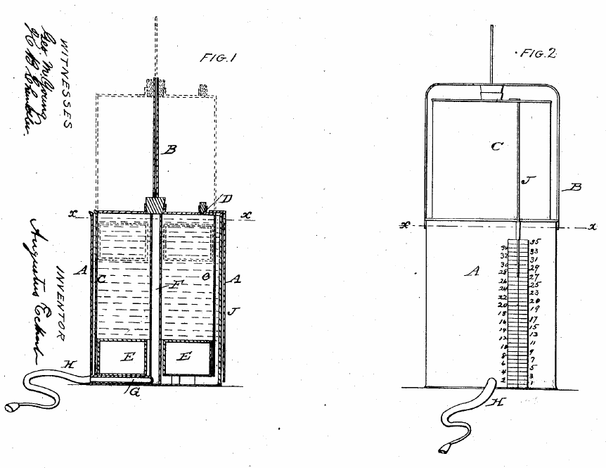
US Patent 26754 by Augustus Eckert of Dayton, Ohio. 1860. A non counter-weighted water-seal spirometer. Two of the patentable features were a guide rod (B) to keep the inner bell straight and an air-filled water-tight chamber in the rim of the bottom of the inner bell (buoy, E) that served the same purpose as a counter-weight. The cork (D) was removed after a vital capacity effort had been made and recorded to allow the bell to be returned to its lower position.
Category Archives: Drawing
Gasometer, Oxygen storage, 1887
From: Oxygen in Therapeutics. By Clyde E. Ehinger. 1887, page 65.
“For administering the combined gases after the method of Doctor Wallian, at least three gasometers are necessary; one for storing the pure nitrous oxide, another for pure oxygen, and a third for a modified mixture.
“It is possible to make one or two gasometers server the purpose, but it will not be found economy to do so, as such an arrangement will necessitate much extra work, and be a constant source of annoyance. One of the greatest objections to having but one or two gasometers is that a supply of both gases – unmixed – cannot be kept on hand – an almost fatal defect, as emergencies are constantly arising which require one or the other of the pure gases.
“The gasometers may be made of zinc or galvanized iron; the latter material, on account of its strength and durability, is preferable for the larger sizes. By using large gasometers it will not be necessary to generate so frequently.
“To a physician who has not a competent assistant to whom he can entrust the generation of gases and care of apparatus, the size of the gasometers will be found a most important item, as much of his time will be consumed in preparing chemicals, generating and commingling the gases.
“For an ordinary practice I would not advise gasometers of less than seventy-five gallons capacity, and where but three are made use of, it would be better to have the one which is used for storing the commingled gases with a capacity from 100 to 150 gallons.”
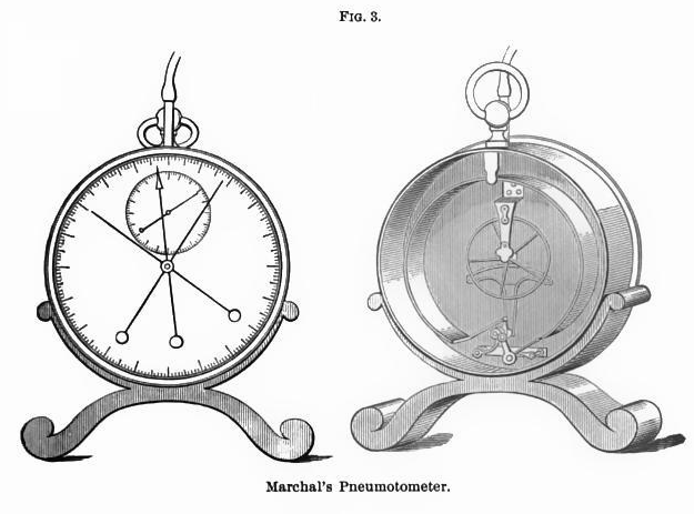
Marchal’s Pneumatometer, 1895
From Physical and Natural Therapeutics by Georges Hayem, 1895, page 21.
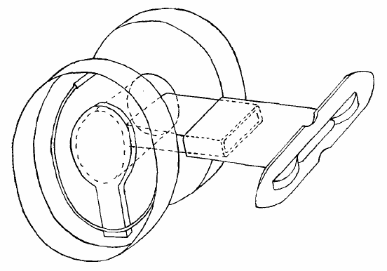
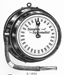
“Marchal’s Pneumatometer consists essentially of a manometric tube, representing almost a complete circle, and communicating at its upper portion with a mouthpiece, from or into which inspiration or expiration is made according as the force of one or the other is to be measured. Index needles serve to mark the diminuation and the increase in pressure (fig 3.).
“If the inspiratory force is to be determined, the needle is placed on the side marked inspiration, and with it also one of the maximal needles. Then, having made a strong expiration, the person applies the lips hermetically against the mouthpiece and takes the deepest inspiration possible. The index needle is displaced, carrying the maximal needle with it; the latter remains at the extreme point, but the former quickly rebounds. The number of degrees indicated by the maximal needle corresponds to the pressure in centimeters of mercury.
“To measure expiration, the stopcocks are reversed, and the needle, carrying the maximal needle with it is placed on the corresponding side. The subject after taking the strongest possible inspiration expires forcibly, and the second maximal needle indicates the result of the effort.
“As a rule the inspiratory effort is less powerful and the expiratory; according to Marchal the ratio is 2 to 3.
“Moreover the result of the effort is not necessarily proportionate to the vital capacity, for the muscles of respiration vigorous in one possessing a relatively small vital capacity, and vice versa.”
Hydro-Spirometer, 1861
From the Hydro-spirometer, by T. Lewis MD., British Medical Journal, Volume 2, 1861, page 255.
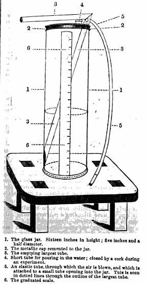
“The new form of spirometer I am about to bring under your notice, is constructed on the principal of displacing a certain quantity of water by an extreme effort of expiration from a graduated glass jar. The jar is graduated in cubic inches, the enumeration proceeding from above downwards, and the results of the experiment is read off the graduated scale.
“Description of the instrument. The jar is about sixteen inches in height and five and a half inches in diameter. It is closed at the top by a metallic cap, which is perforated by three holes, into which are inserted corresponding tubes, as will be seen in the diagram.
“While in operation, the instrument is laid almost horizontally on the table, having been previously filled with water up to the level of the mark which indicates the commencement of the scale. The glass mouthpiece at the extremity of the elastic tubing is then placed in the mouth, and, after an extreme inspiration, the fullest expiration is made. There is no necessity for any precautions at the close of the expiratory effort. After the effort, the instrument is replaced in the erect position, in order to read off the amount of air introduced into the jar. There is no necessity for any correction on account of temperature, as it assumed that the air proceeding from the lungs is nearly always the same temperature.”
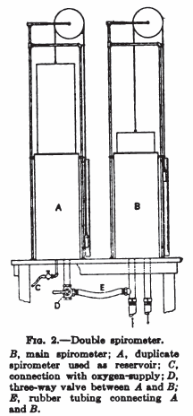
Double spirometers for exercise testing, 1922
Mouthpiece and Valve, 1918
From: Yandell Henderson, AND INDIRECT CALORIMETRY VI. THE RESPIRATORY EXCHANGE APPLICATIONS OF GAS ANALYSIS: ARTICLE: J. Biol. Chem. 1918, 33:47-53.
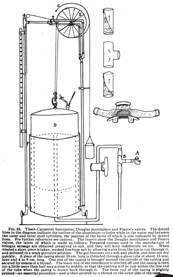
“A form of valve which has proved convenient has recently been devised at the University of Minnesota by professors A.D. Hirschfelder and E.D. Brown. By their kind permission a diagram of two of these valves arranged for inspiration and expiration on a T-tube is shown in Fig. 2. Each valve is made of a large tin salve box with a disk of sheet rubber inside, held in place by a ring spring wire soldered to the box at one point. The crack around the box is made tight with adhesive plaster. In the figure the cover of one valve is removed to show the rubber and wire.”
