From an undated publicity photo.
From an undated publicity photo.
A Collins basal metabolism system using a dry spirometer. From ‘A Catalog of Pulmonary Function Equipment and Accessories’, W. E. Collins Inc., page 17.
From an undated publicity photo, likely from around 1940.
Undated publicity photo, probably from around 1948.
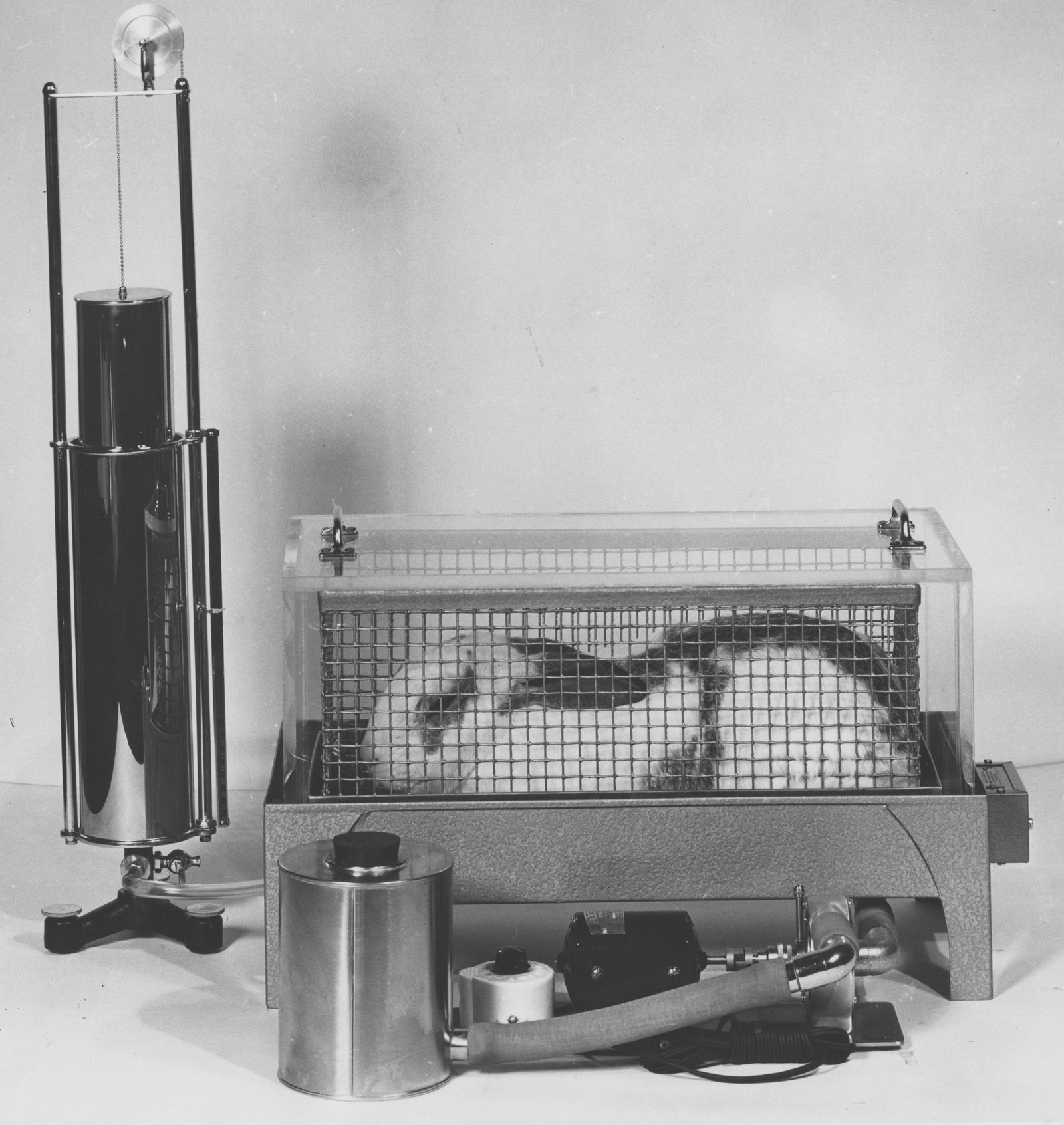
Small animal basal metabolism system with a 1.4 Liter spirometer. From ‘Collins’ Catalog of Pulmonary Function Testing Instruments”, undated by likely from around 1978, page 1-49.
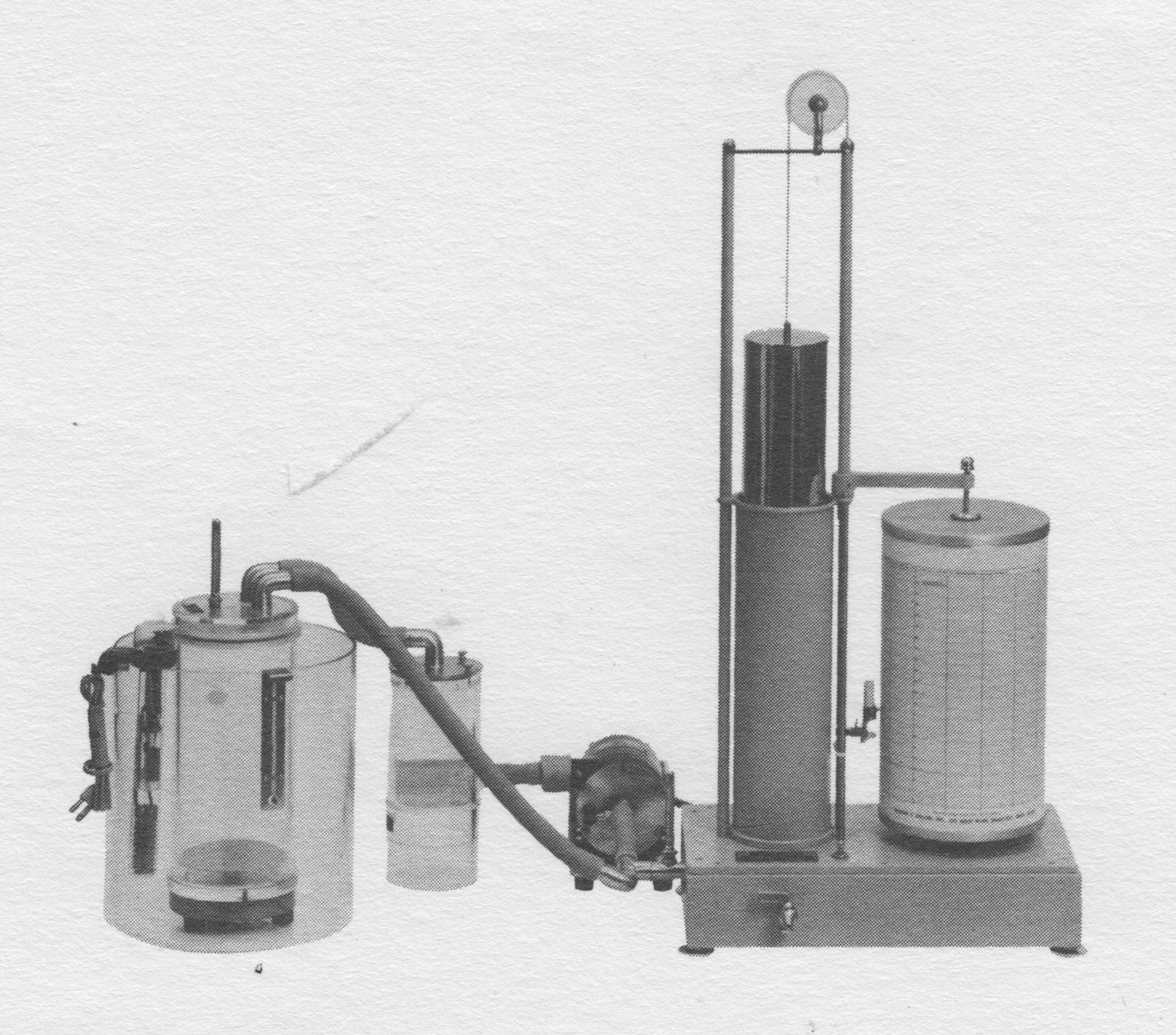
From “Methods in pulmonary physiology”, by Bertels H, Bucherl E, Hertz CW, Rodewald G, Schwab M. Translated by Workman JM. Hafner Publishing Co., 1963, page 30. Undated, but probably from the mid-1930’s.
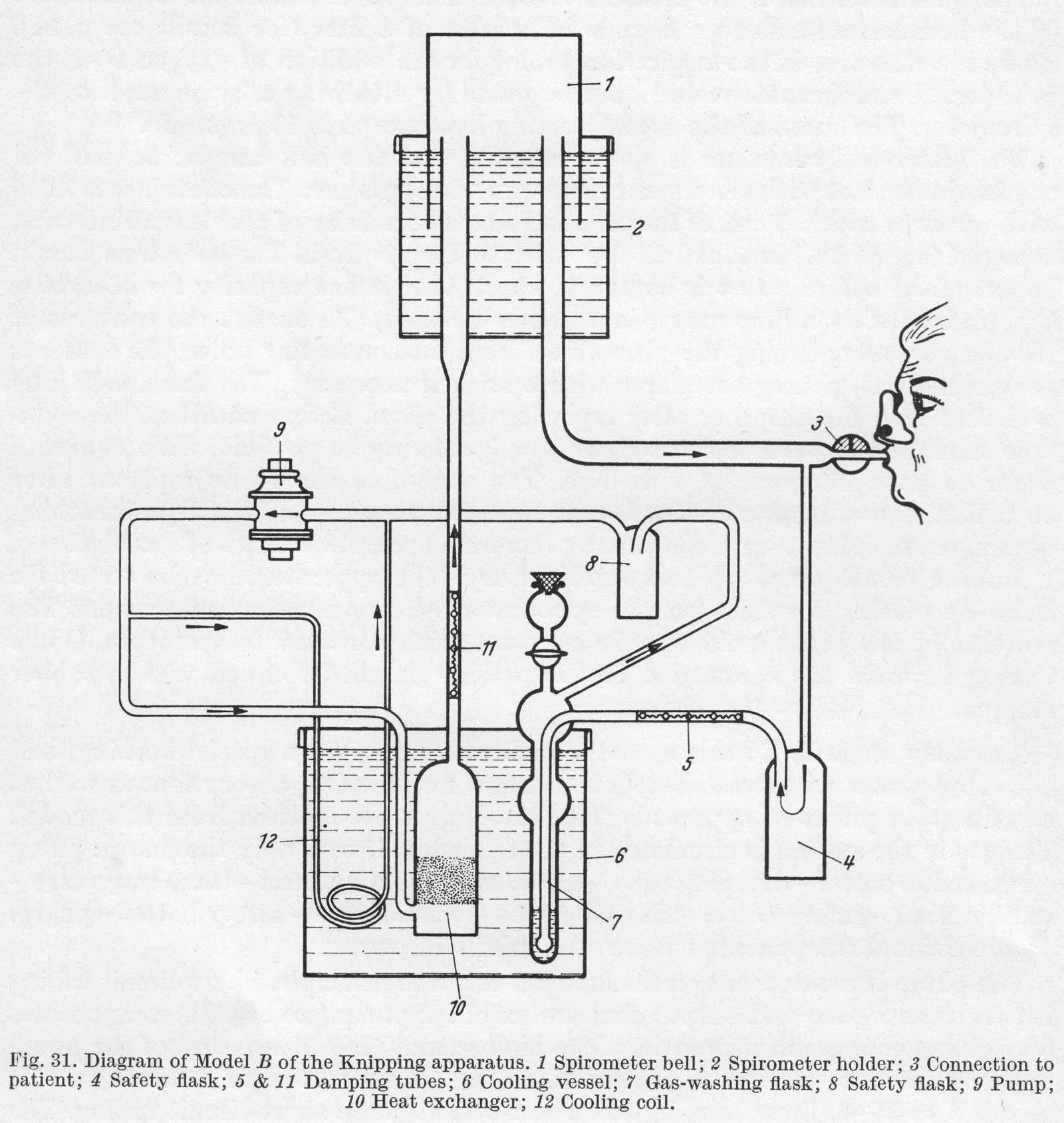
 From “Methods in pulmonary physiology”, by Bertels H, Bucherl E, Hertz CW, Rodewald G, Schwab M. Translated by Workman JM. Hafner Publishing Co., 1963, page 24.
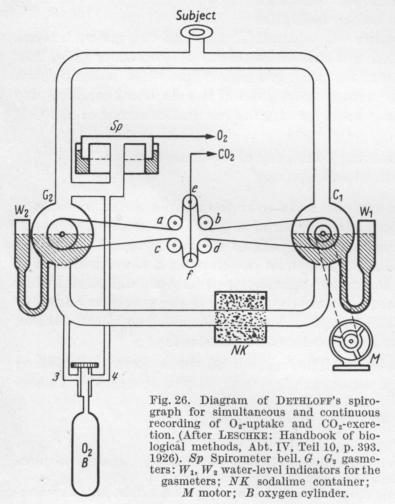
“In Dethloff’s apparatus, the difference in volume of expiratory gases before and after absorption of CO2 is used to measure CO2 output. To this end two gas meters are placed in the circuit, one proximal and one distal to the CO2 absorber. The difference in reading between the two gas meters provides a continuous measure of CO2 output.”
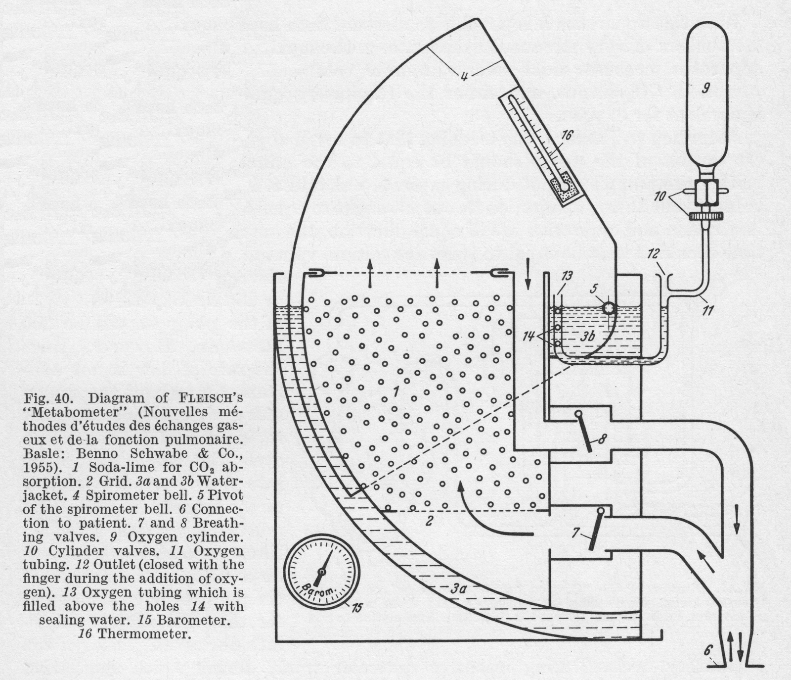
From “Methods in pulmonary physiology”, by Bertels H, Bucherl E, Hertz CW, Rodewald G, Schwab M. Translated by Workman JM. Hafner Publishing Co., 1963, page 39.
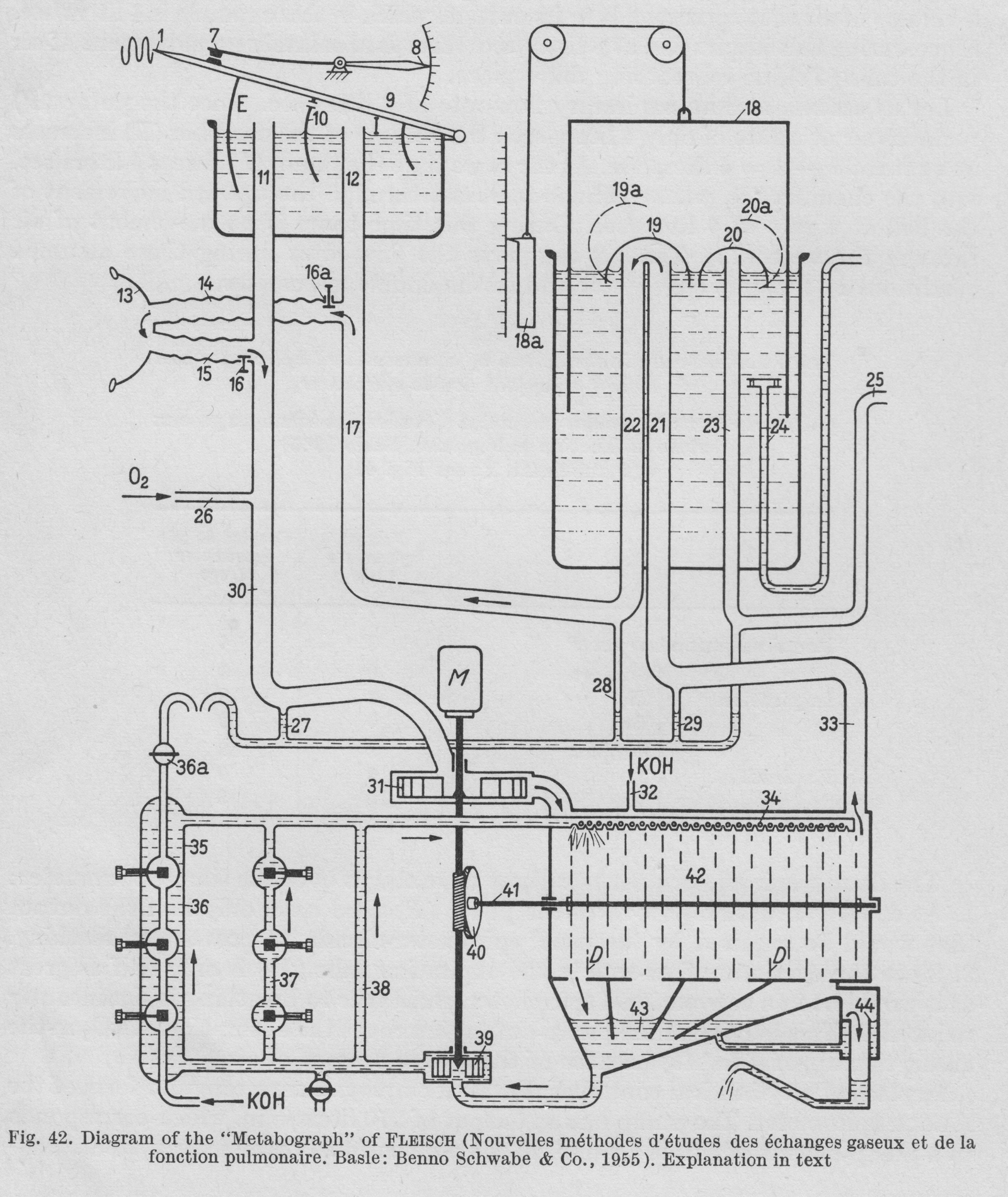
From “Methods in pulmonary physiology”, by Bertels H, Bucherl E, Hertz CW, Rodewald G, Schwab M. Translated by Workman JM. Hafner Publishing Co., 1963, page 42.
“Figure 42. is a diagrammatic representation of the construction of the apparatus. A motor (M) drives the pump (31), which sends air int the CO2 abdorbant chamber (42). Freed of CO2, the air passes by way of the tube (33) into (21), then under the valve (19). From here it is led through tubes (22), (17), (14), (15), (30) and returns to the pump (31). During inspiration the bell (9) of the double spirometer sinkes and a corresponding volume of air passes out of (I) through tubes (12) and (14) into the lungs, while the pump removes an equal volume from the chamber (E) through tubes (11), (30). During expiration, the volume of air that leaves the lungs travels by way of (15) and (11) to chamber (E), while the corresponding volume passes into chamber (I) through (17) and (12). This the bell (9) rises. The partitioning septum (10) is pierced by a small opening so that some air is always passing from chamber (I) into chamber (E), preventing accumulation of CO2.
“Volume stabilization is achieved through an electrical contact (7). When contact is broken, oxygen is added to the system by a pump through (26). This establishes the bell in the middle position, and maintains the O2 concentration in the system practically constant. When the bell touches the contact (7), the total volume of the system is 32 liters.
“In the absorption chamber (42) there are rotating discs, over which KOH runs. This arrangement provides the larges possible surface area for CO2 absorption. The KOH is collected in a sump (43), removed hence by a pump (39) and sent back to the distribution chamber (34) by three parallel routes (38), (37) and (36). Recording of CO2 production is based on the measurement of the electrical conductivity of the KOH. Throughout the period of study the conductivity of the KOH is held constant. When the degree of alkalinity of the KOH is reduced by the expired CO2 resulting in reduced conductivity, fresh KOH is added through the side tube (32) until the original conductivity is restored. Thus the CO2 production of the subject under study is determined directly by the amount of fresh KOH that has been added.”
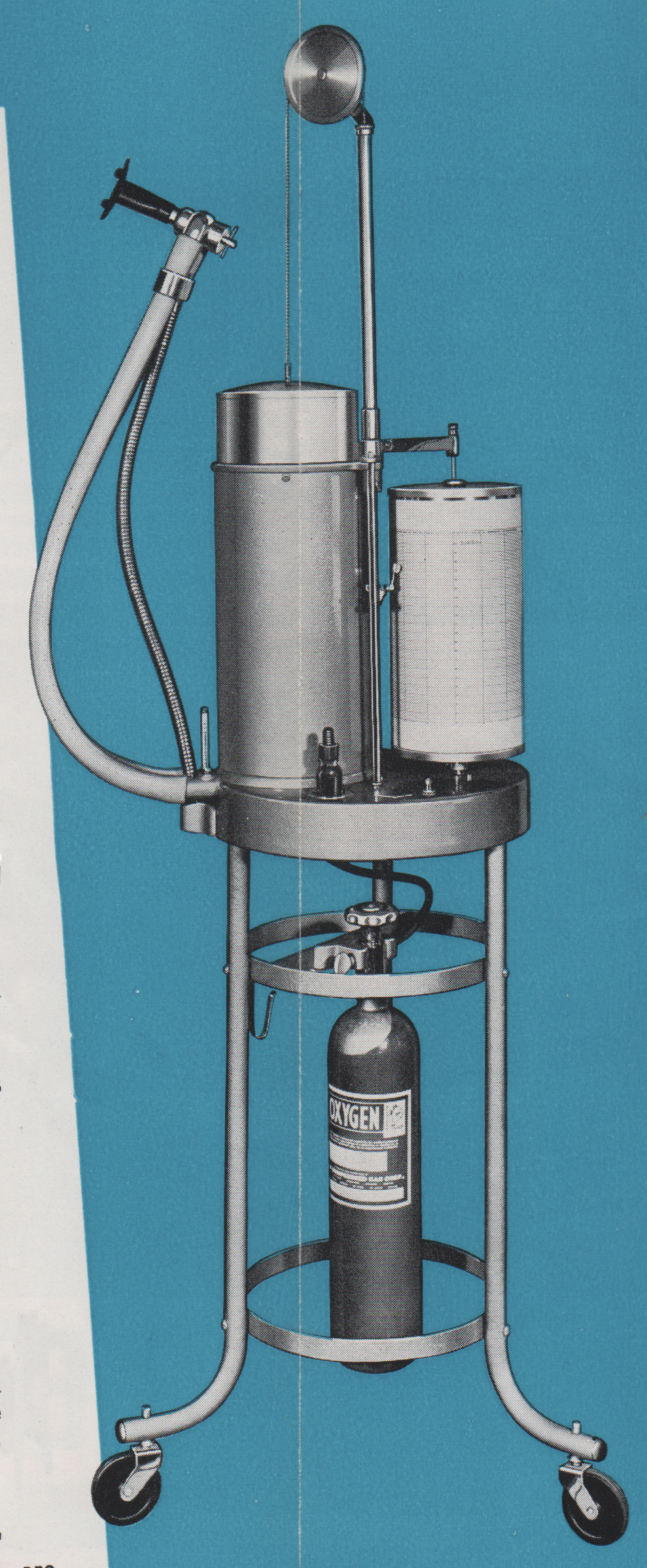
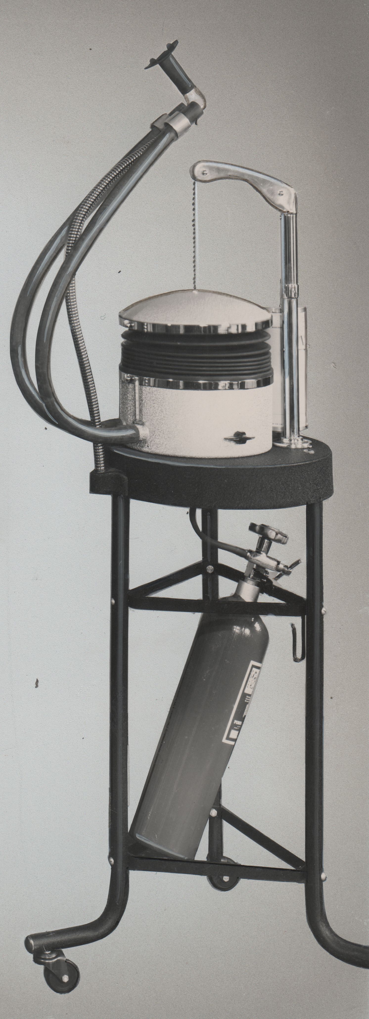
From a Collins sales brochure printed in 1949.