From “Directions for operating a Collins chain-compensated gasometer”, Second Edition Cat. No. P-469. Warren E. Collins, Inc. May, 1967.
From “Directions for operating a Collins chain-compensated gasometer”, Second Edition Cat. No. P-469. Warren E. Collins, Inc. May, 1967.

From “Directions for operating a Collins chain-compensated gasometer”, Second Edition Cat. No. P-469. Warren E. Collins, Inc. May, 1967.
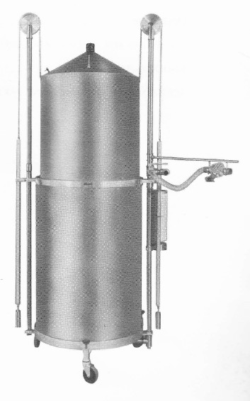
“PRINCIPLE OF CONSTRUCTION
“The Gasometer is made of stainless steel with an outer body and an inner body space about two inches apart to form a water seal for the Spirometer bell fo “float” in. The inner body is also shapes to occlude most of the dead space; and the whole unit is mobile on its own casters.
“CHAIN COMPENSATION
“When the Gasometer is filled with water to the petcock level, and the Spirometer bell is in its lowest position, the bells weighs less than when it is in its highest position, because of the buoyant effect of the water. To automatically compensate for this increasing weight so that the bell will be perfectly counterbalanced throughout its travel, the Collins Gasometer uses a chain to connect the bell to the main counterweight. Thus, as the bell rises, more segments of chain pass over the pulley. As the bell becomes heavier, so does the counterweight in direct proportion, with the result that almost perfect balance is achieved in all positions.
“ATTACHMENTS
“The Gasometer is fitted with the following standard attachments:
“Thermometer – indicates the temperature of the gas within the bell to facilitate various gas volume calculations.
“Auxillary Counterweight – removable so that the Spirometer maybe emptied quickly bu gravity.
“Two-Way Valve – permits addition or subtraction of gas while the patient is breathing. May also be used for sampling.”
Adjustable Height Knob – 120 Liter model: permits telescoping of the chain and pulley downwards. 350 and 600 liter models: pulley supports unscrew. Facilitates transportation and permits moving through low doorways.
“Leveling Screws – assures vertical position of the Spirometer so that the bell will not contact the side of the outer body.
Breathing Branch Assembly – supplies with the 120 liter Gasometer only. It serves as a support for the J-2 Valve or other breathing valves and tubing when the patient is to breathe directly into the Spirometer either from a sitting position or from the bedside.”
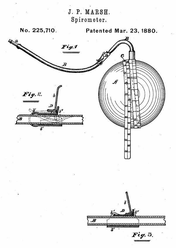
From patent number 225, 710 by J.P. Marsh, Mar 23, 1880.
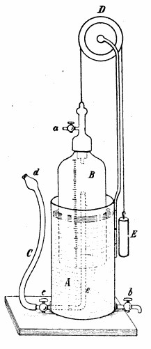
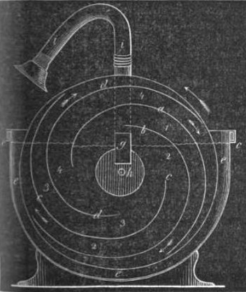
“A is a flexible bag or receiver, made of india-rubber, by preference, and expansible to such a degree as to be capable of being distended with facility by air expelled from the human lungs into the receiver.
“B is a flexible tube coupled to the part A. The tube B should be provided with a mouth-piece at its free end, as indicated at a.
“C is a gage or measuring-tape, connected at one end to the part A, preferable at the place where the tube B is coupled thereto.
“In using this device as a spirometer, the piece a is inserted into the mouth of the user, and the remaining part held in any convenient way which will not interfere with the inflation of part A. The part A may then be inflated by being blown into, and as soon as the capacity of the lungs is thus sufficiently tested the tube B should be pinched together to prevent the air from escaping from the receiver. The gage C should then passed around the inflated receiver, as indicated in Fig. 1, and where the fixed end of the gage meets the encircling part thereof will be found figures indicating the amount in cubic inches of air in the receiver, whether there be more or less therein, being understood that part C is graduated for that purpose, and that it will be taken up more o less by encircling the receiver, according to the amount of air forced therein from the lungs of the user. In this way the user may test the capacity and strength of his lungs, and note their condition in these respects, and a proper use of the device will, it is believed, be found to be a healthful exercise for the lungs.”
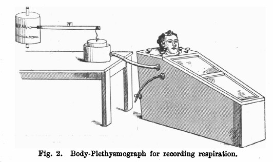
From Johns Scott Haldane and John Gillies Priestley. “The regulation of the lung‐ventilation.” The Journal of physiology 32.3-4 (1905): 225-266.
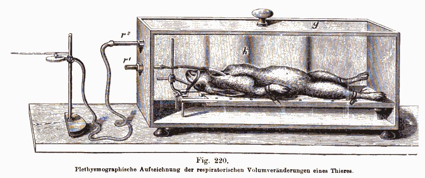
“In investigating the normal respiratory ventilation is is evidently important to avoid breathing through tubes, vales, etc,. and equally important to have a definitive quantitative record of the air breathed. In order to attain these two objects we employed a body plethysmograph arranged as follows (see Fig. 2).
“The box of the plethysmograph was of such a size and shape as to include as small a space as practicable, and yet enable the subject of the experiment to sit in perfect comfort. Its internal dimensions were as follows:–Floor, 45 inches long. Back, 19-1/2 inches wide x 24-1/4 inches. Lid, 19-1/2 inches wide behind x 16 inches in front x 14-3/4 inches. Sloping front, 37-1/4 inches x 16 inches x 10 inches. End, 10 inches wide by 12-1/2 inches high.”
“The lid was in two parts, with a circular aperature in the middle, through which the neck passed. Thumb-screws were provided for fastening it to the box, and all joints, screw-holes, etc., were made tight with “plasticene” (modelling wax). Air-tight connection was made between the neck of the subject and the lid of the box by means of a rubber collar with a broad flange, which was slipped over the head, and fitted the neck as tightly as possible without causing congestion. The flange was pressed down tightly on a layer of plasticene on the lid of the box by a ring of wood. This wooden ring was of course in two pieces, and was pressed down on the collar by means of thumb screws.
“In the side of the box were two holes into which tubes were fitted by means of corks. One of these was connected with a rubber tube for letting air into or out of the box to adjust the level of the writing-point and counteract, if necessary, the influence of rise of temperature in the box. The other was connected with the recording apparatus by means of rubber tubing 1 inch in diameter.
“The recording apparatus itself was arranged as shown in the figure. The cylincer suspended to the balance beam was of light tin plate. Two sizes were used — of 8 and 12 inches diameter — according to the depth of breathing expected. As the up and down movements of the writing-point traced on the smoked cylinder were proportional to those of the bell-jar.”
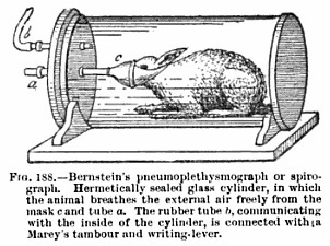
From Human Physiology, Volume 1, By Luigi Luciani, published by Macmillan and Company, 1911, page 425.
“The same effect may be obtained when the animal is breathing free air, while enclosed within a hermetically sealed glass cylinder (Knoll). A tube tied in the trachea, or fitting tightly over the mouth and nostrils of the animal, passes through the wall of one box and communicates with the external air. The internal air of the box is connected by means of a second tube with a recording tambour, and traces, like a plethysmograph, the variations in the total volume of the animal , corresponding to the inspiratory and expiratory movements. The simplest application of this method is that of Bernstein, represented in Fig. 188.
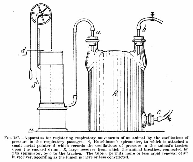
Human Physiology, Volume 1, By Luigi Luciani, published by Macmillan and Company, 1911, page 422.
“The name tidal air is given to the volume of air which enters and leaves the pulmonary air passages during a normal inspiration and expiration. It can be measured by a well calibrated and graduated glass bell, which Hutchinson (1860) termed a spirometer (Fig. 187). A properly constructed gasometer, which offers minimal resistance to the passage of air can be substituted.”
From Physiologische graphik, By Oskar Langendorff, published by F. Deuticke , 1891, page 268. The plethysmograph is connected to a Marey tambour.
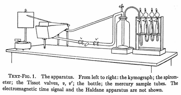
From “The respiratory mechanism in pneumonia”, by Newburgh LH, Means JH, Porter WT, The Journal of Experimental Medicine, Volume 24, page 583, 1916. The spirometer is a Krogh type.
“A portion of the apparatus employed is shown in Text-Fig. 1. The tracheal canulla of the animal in which the respiratory reaction was to be measured was joined to a rubber tube placed between two Tissot valves connected in such a way that the animal breathed into a spirometer and out of a bottle connected in turn with the spirometer, so that the lungs, the spirometer, the bottle and the connecting tubes formed a closed system. Evidently by this arrangement the volume of air passing into and out of the chest was recorded by the spirometer, while the carbon dioxide exhaled by the animal constantly accumulated in the closed system. Samples of the air thus enriched with carbon dioxide were withdrawn at frequent intervals by the mercury tubes shown in Text-fig. 1. As each sample was taken, a mark was made on the spirometer record (the electric time-signal is not shown in Text-fig. 1). As the carbon dioxide in the respired air increased, the spirometer curve became deeper, until the maximum was reached.”
From: Lehrbuch klinischer Diagnostik und Untersuchungsmethodik für Studierende, Medizinalpraktikanten und Aerzte, by Theodor Brugsch and Alfred Schittenhelm, published by Urban & Schwarzenberg, 1921, page 17.
From Jahrbücher der in- und ausländischen gesammten Medizin, Volume 67, Published Wigand, 1850, page 43. A water-sealed gas meter.