From: Solandt OM, Ridout JH. The duration of the recovery period following strenuous muscular exercise. Proceedings of the Royal Society of London, 1933: 113: 327-344, page 329.
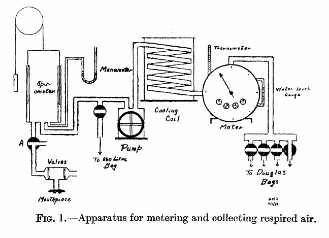
“As shown in the diagram, the air expired by the subject is first collected in the 10-liter spirometer. From the spirometer it is pumped through a cooling coil, through the meter, and then into a Douglas bag. In this way the air is metered before entering the bag, and the bag is only used to collect the air so that a sample may be taken.
“The valves used were of the conventional type, consisting of a circular rubber flap, seating on a metal ring. They were tested before each experiment. The pump used was of the movable blade rotary type and was driven by an electric motor. The meter used was a Sargent wet test gas meter. This type of meter is very sensitive to changes in water level, as Krogh (1929) has pointed out, hence the water level was checked before each experiment. The correct water level was determined by checking the meter against a small Bohr meter which has been calibrated by displacement of air. The accuracy of the Sargent meter was guaranteed by the makers to within 1 percent at rates of flow up to 50 cubic feet per hour. During the experiments the rate of metering was never allowed to exceed this value. The cooling coil was used to prevent too great a rise in meter temperature owing to the passage of warm expired air through the meter. The effectiveness of this device is shown by the fact that the meter temperature seldom changed as much as one degree during an experiment (2 to 3 hours). By cooling the air, complete saturation with water vapor was also ensured.”
From: Meneely GR, Kaltreider NL. The volume of the lung determined by helium dilution. Description of the method and comparison with other methords. Journal of Clinical Investigaton, 1949 28(1): 129-139, page 130.
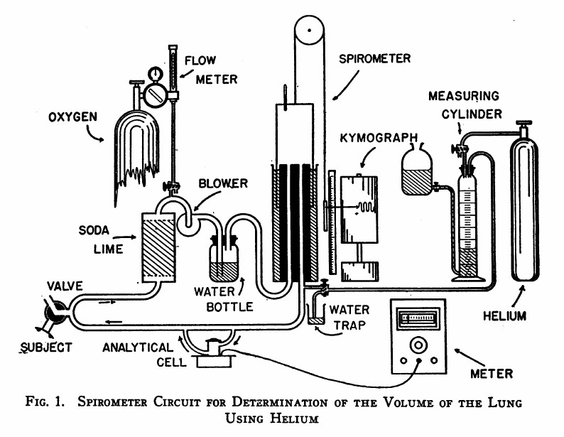
“The spirometer circuit is diagrammed in Figure 1. The seven-liter cylindrical spirometer with obliterated internal dead space write the respiratory tracing on a kymograph drum. The volume of the spirometer may be read from the scale and pointer and, by transfer, from the respiratory tracing itself. The subject is connected to the circuit through a rubber mouthpiece on a three-way valve. The expired air passes vertically through a soda-lime canister for the most efficient absorption of carbon dioxide. Oxygen may be added at any desired rate through the diaphragm type flow control and meter on a tank of “medical” oxygen. A blower impels the expired air through the water bottle which contains many glass bead to break up the bubbles, and prevent disagreeable bumping due to large bubbles. Provision is made for the introduction of helium at the spirometer outlet. Part of the return flow shunts through the analytical cell and returns via the cell outlet to rejoin the return stream. The pressure differences in different segments of the circuit are small: slight negative pressure obtains between the soda-lime and blower, and positive pressure elsewhere. The soda-lime and the water bottle isolate the the blower to a degree, preventing vibration of the air column at the mouthpiece.”
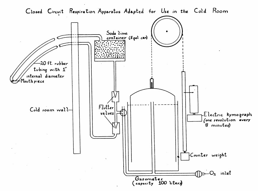
System for measuring basal metabolism in a cold environment. From: Clothing Test Methods, National Research Council (U.S.). Subcommittee on Clothing, National Academies, 1945, Page 19.