Tag Archives: Krogh

Spirometer, Krogh, 1934, Basal Metabolism Test

Spirometer_Krogh_1934_Minute_Ventilation_Test

Found at Europeana.Eu.  From an educational film entitled “Methods of measuring metabolism and basal metabolism Krogh and Douglas bag”, Produced by the Department of Physiology, Cambridge University, 1934.

A basal metabolism test with a Krogh spirometer.  Subject is breathing through soda-lime and the disappearance of oxygen is monitored on the kymograph drum.

Spirometer, Dual Krogh for oxygen consumption and CO2 production, 1924

Spirometer_Dual_Krogh_1924

From: CLXXII: An apparatus for the graphical recording of oxygen consumption and carbon dioxide output, especially adapted for clinical work. By H.C. Hagedorn.  Biochemical Journal, 1924, page 1304.

“Figure 2 shows the apparatus in a convenient form which has been in use for about two years with complete satisfaction. The gas meters and spirometers are arranged in a common water-bath, the spirometers recording on a common drum, most conveniently with ink of different colours. The water-bath is fitted with an overflow tube to secure constant water level; it contains about 100 kg. water, and the expired air is led through a pipe of considerable length which is immersed in the bath to cool the air to the temperature of the bath before it enters the gas meter. From the service pipe to the spirometer (B) there is a wide pipe to secure that every change in air pressure caused by the respiration is taken up promptly by the spirometer (B), so that there can be an absolutely constant in the gas meter I.

“The accuracy of the results largely depends on the care with which the spirometers are balanced; every change in the air pressure in one of the spirometers will affect the water level in the corresponding gas meter and so disturb its accuracy.  The spirometers are therefore arranged on special bearings and balanced with a double set of counterbalances, a large one for gross and a small one for fine adjustment. The counterbalances are adjustable horizontally and vertically, thus allowing convenient compensation for buoyancy of the spirometer.”

Spirometer and metabolic apparatus, Krogh, 1916

Spirometer_Metabolic_Apparatus_Krogh_1916

From: The respiratory exchange of animals and man by August Krogh, 1916, page 40.

“Krogh’s apparatus (fig. 15) [1913] which is a modification of an instrument constructed by Haldane and Douglas [1912], is furnished with valves and the air is circulated by the respiratory movements of the subject.  Carbon dioxide is absorbed in a vessel containing a charge of soda lime sufficient to absorb 1000 liters of carbon dioxide, a quantity produced by a man at rest in about 70 hours.  The recording spirometer gives a quantitative record of the respiratory movements and governs the admission of oxygen by closing an electric circuit at (5).  The oxygen from the cylinder is measured by the meter which records electrically by closing a circuit each time a certain quantity has been admitted.  Whenever an experiment has to be extended over a long period, or if the absorption of oxygen is very rapid as during heavy muscular work, the oxygen admitted must be nearly pure to prevent the oxygen percentage in the small apparatus from falling.

“The apparatus in its present form does not allow the direct determination of carbon dioxide.  When such determinations are desired samples of expired and inspired air are drawn from the vessels (2) and (10).  The respiratory quotient is determined by analysing these samples for carbon dioxide and oxygen.  The total respiratory exchange can also be measured over short periods by by multiplying the analytical results by the ventilation as measured from the graphic record.”

Spirometer, Gas Meter Calibration, 1920

Spirometer_Calibration_Krogh_1920

From: The calibration and accuracy of gas meters. By August Krogh.  Biochemical Journal, 1920, Chapter XXIX, page 19.

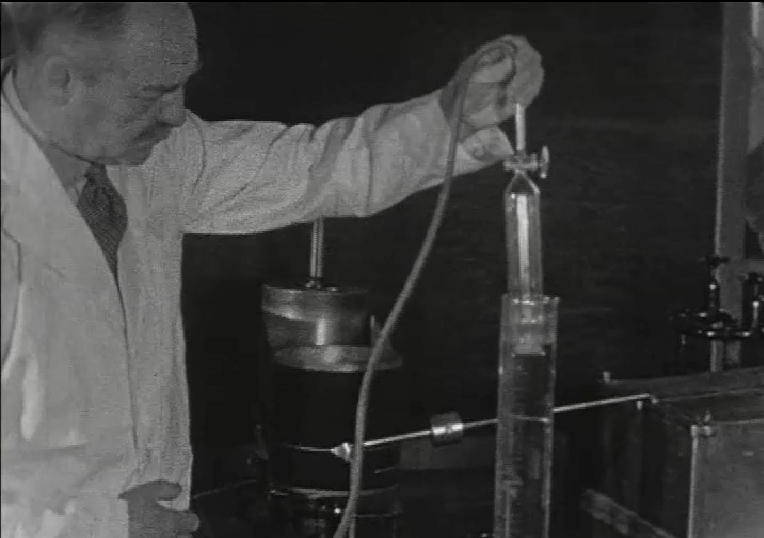
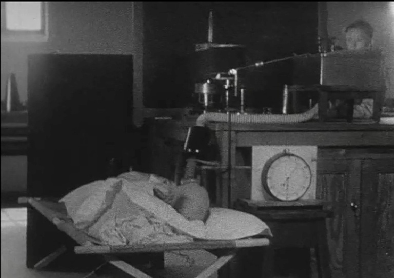
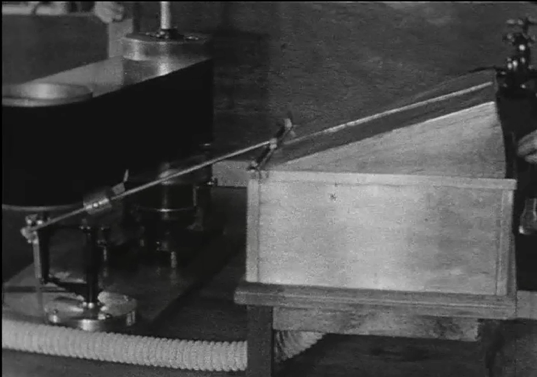
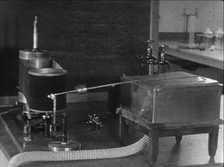
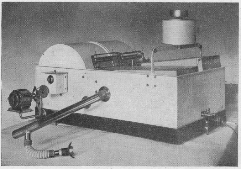
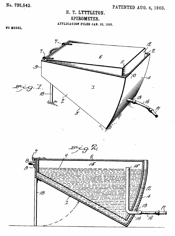
“The calibration spirometer (fig 1) is an adaptation of a similar instrument employed by the Dannsk Maalerfabrik, the chief improvement being that I have arranged an automatic record of the volume per revolution of the meter calibrated.  The drum (1) which is as nearly as possible cylindrical is suspended by a band of soft steel and counterbalanced by the adjustable weight (2).  It moves up and down with a minimum of friction.  When the drum is in its highest position the weight can be held by an electromagnet (not shown in the figure) from which it can be released at any desired moment by breaking the current.  Along the steel band a fine brass wire is arranged carrying a number of lead weights (3).  These can be displaced along the wire and a complete equilibrium in all positions of the drum can thus be secured.  When the weight (2) is reduced, any desired pressure up to 20 mm. water can be produced in the spirometer.  The revolving fan (4) which can be driven from outside is used for mixing purposes.  In calibration work with air it is revolved for a few minutes when the spirometer has been filled, to secure a uniform temperature and perfect saturation of the air with water vapour.

“The drum is painted inside and out with a hydrophobe compound so that its volume will not be altered by water absorbed to its wall.  This detail is very important. When left in contact with water, ordinary paint will take up a considerable volume of water which cannot drain off.  According to experiments a painted tinplate continued to gain in weight while immersed in water for a couple of months, ultimately to the extent of 2.5 gm per 100 sq. cm.  Such an increase would in my spirometer diminish by 3.5 cc the effective volume per cm.

“The spirometer drum has been calibrated by measuring a large number of internal diameters (133) evenly distributed over the whole length and circumference of the drum.  These measurements have given as the average diameter 450..135 +/- 0.09 mm or a volume of 1591.4 cc per cm. height.  When the drum is used in the spirometer a lowering of 1 cm. will drive out a little more air than the corresponding volume of the drum because the surface of the water in the reservoir will be raised when 1 cm. of wall of the the drum is lowered into it.  The volume of 1 cm. of the wall of the drum is 9.4 cc.  The rise in the water level will of, course, correspond to 9.4 cm., but since only 19.0% of the water surface is inside the drum the extra volume corresponding to 1 cm. will be 19/100 x 9.4 = 1.8 cc and the effective volume of 1 cm. is therefore 1593.2 cc.  A further correction for the volume of the hydrophobic paint and for water adhering to the inside reduced the volume to 1593.0 cc.  This latter correction is of course a little arbitrary.  When the drum has been rapidly raised the water must be allowed to drain off for about 5 minutes before a practically constant volume is attained.  The water adhering to it at first may amount to a couple of cc. per cm. or more.”