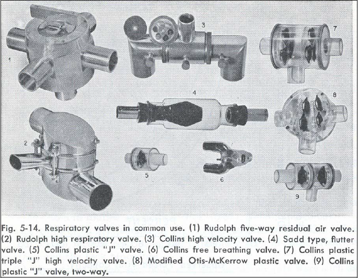
Breathing valves available in the USA in 1963. Attrributed to an article authored by Consolazio, Johnson and Pecora. From: page 40 of of a 2003 doctoral dissertion by Yaser Mahfouz Atwa Saad Elgohari.
Breathing valves available in the USA in 1963. Attrributed to an article authored by Consolazio, Johnson and Pecora. From: page 40 of of a 2003 doctoral dissertion by Yaser Mahfouz Atwa Saad Elgohari.
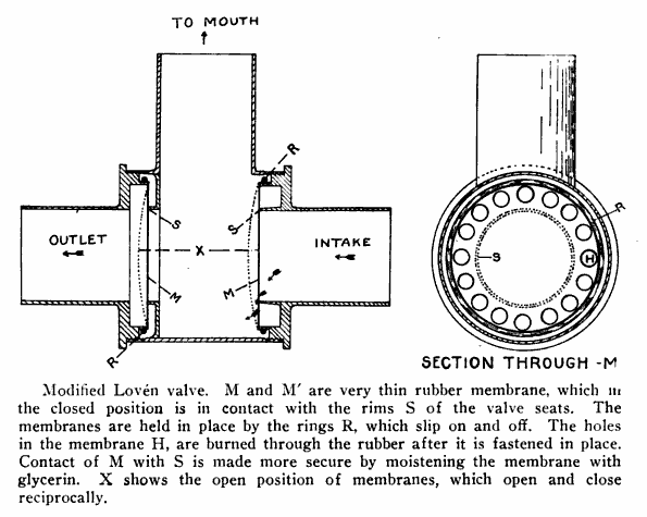
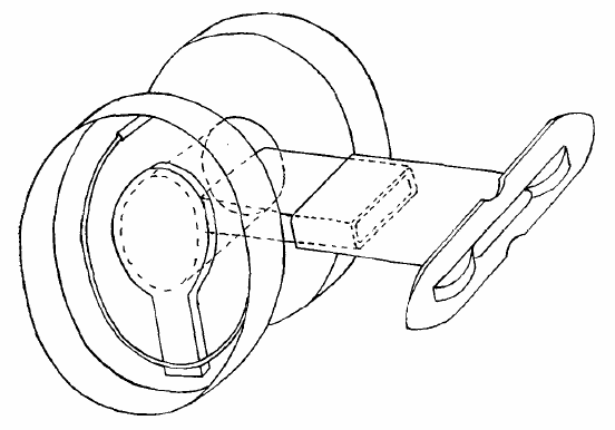
From Archives of Internal Medicine, Vol 28, page 849, 1921. Manufactured by G.F. Soderstrom.
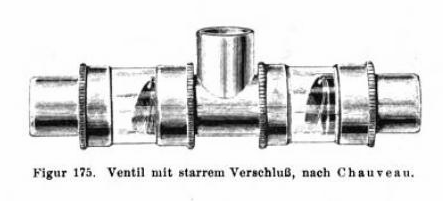
Physiologische Übungen und Demonstrationen: für Studierende By Robert Tigerstedt. Published by Taylor & Francis , 1913. Page 187.
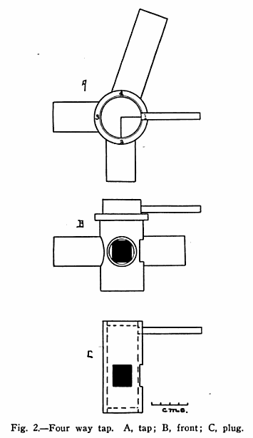
From: Spirometer measurement of oxygen consumption by the rebreathing method. By Charles Claude Guthrie, Archives of Internal Medicine, Volume 28, 1922, page 843.
“The tap (Fig. 2) serves to connect the spirometer through the absorber with the pump, the subject or the outside air. The rotating portion of the tap is hollow and provided with two openings spaced 90 degrees apart.
“In the first position of the tap, the absorber is shut off and the subject breathes room air. Position two is a quarter turn (clockwise, i.e. to the right) and switches the subject to the absorber and thus to the air in the spirometer, at the same time closeing the opening to the outside. Position three connects the absorber with the pump, and position four connects the pump to the outside air.”
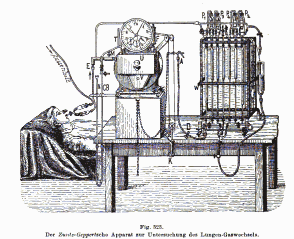
From: Methodik des Energiestoffwechsels, by Von J. E. Johansson, Handbuch der biochemischen arbeitsmethoden, Volume 3, Part 2, Edited by Emil Abderhalden, published by Urban & Schwarzenberg , 1910, page 1156.
Included a mouthpiece, one-way valves, dry gas meter and chemical gas analyzer.
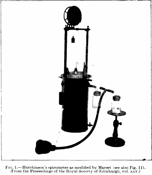
From: The Harvey Lectures, Volume 3, 1909, page 226. A standard Hutchinson-style spirometer outfitted with what appear to be Muller (water seal) one-way valves and a mask for measuring tidal or minute volume.
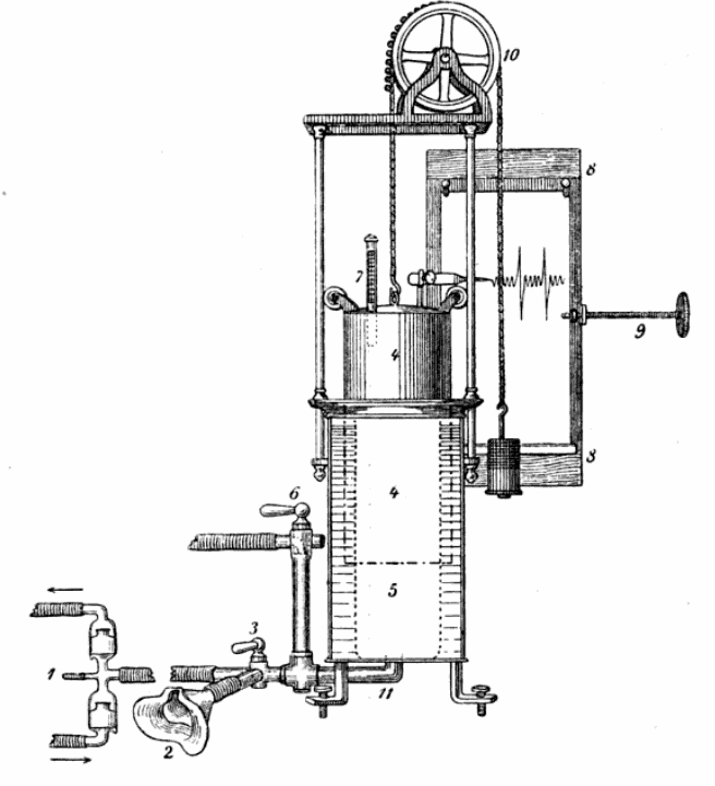
From: German archive for clinical medicine , Volume 88, 1907, Page 391. Note the breathing mask and one-way valves. Note also the pen writing on graph paper which was apparently moved horizontally by a screw. Manufacturer unknown.
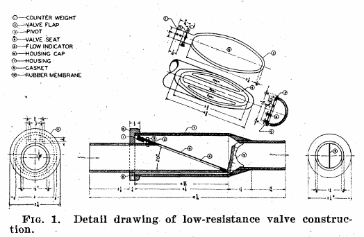
From: A low resistance valve and indicating flowmeter for respiratory measurements. By Leslie Silverman and Robert C. Lee. Science 1946; 103: p537.
“It can be noted that the valve flap angle is very low (20 degrees), and thus very little change in direction is necessary in permitting air to pass, once the valve begins to open. The area of the valve flap surface is large, and hence a low pressure will exert enough force to open it. The weight of the valve flap is offset by the counterweight. This counterweight (4 grams) was proportioned to give a low opening pressure and yet allow an adequate amount of of positional movement in the complete valve. The seating surface of the valve is limited to the small longitudinal braces and edges of the seat periphery. In order to reduce the adhesive effect of the rubber membrane when wet, the seating surfaces are dusted with talcum powder. This powder prevents the rubber membrane and Lucite seating surfaces from wetting and also helps preserve the membrane.”

The Rosling valve was originally patented in England prior to World War I and was used in mining and gas masks. This drawing is from Cecil Rosling’s American patent application. The valve had low resistance and unlike many valves of the time, the rubber diaphragms themselves provided the spring action. The Rosling valve was used extensively in physiological research from the 1920’s to the 1950’s.
From: Yandell Henderson, AND INDIRECT CALORIMETRY VI. THE RESPIRATORY EXCHANGE APPLICATIONS OF GAS ANALYSIS: ARTICLE: J. Biol. Chem. 1918, 33:47-53.
“A form of valve which has proved convenient has recently been devised at the University of Minnesota by professors A.D. Hirschfelder and E.D. Brown. By their kind permission a diagram of two of these valves arranged for inspiration and expiration on a T-tube is shown in Fig. 2. Each valve is made of a large tin salve box with a disk of sheet rubber inside, held in place by a ring spring wire soldered to the box at one point. The crack around the box is made tight with adhesive plaster. In the figure the cover of one valve is removed to show the rubber and wire.”