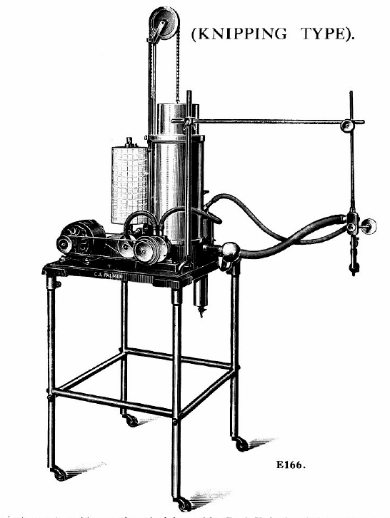
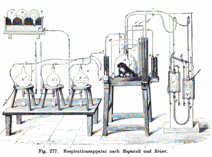
From Palmer, C. F. 1934. Palmer Research and Students’ Apparatus for Physiology, Pharmacology, Psychology, Bacteriology, Phonetics, Botany, etc.: Manufactured by C. F. Palmer (London) Ltd., Myographic Works, 63a, Effra Road, Brixton, London, S.W. 2. England, page 88.
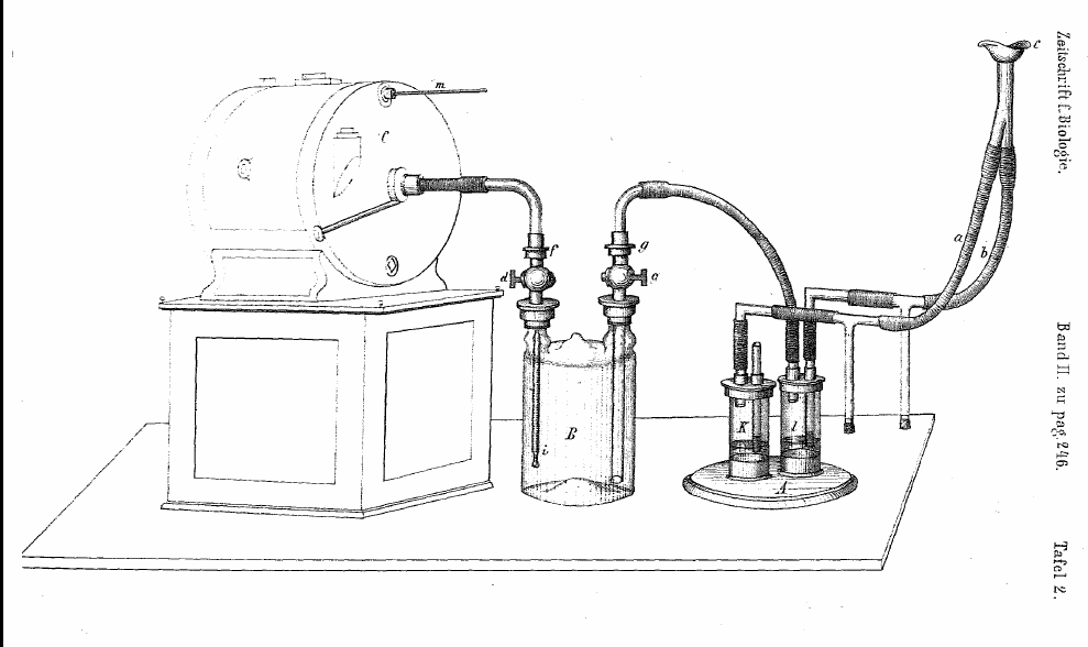
“The several parts of the assembly as shown in the outline drawing herewith, consist of the following: —
“1. The Spirometer A, the float of which is carefully balanced by a chain comensated counterpoise.
“2. The rotary air pump P, works on the centrifugal principle, and is driven by the electric motor M.
“3. The glas flask F contains the K.O.H. solution in the bottom, depending into this is a tube with a perforated bulb at one end, so that air from the pump is forced through the solution and to the outlet in the side. At the top of the flask is a container for the H2SO4, which is released through the cock C, when it is desired to ascertain the C.O2 produced.
“4. The three-way cock T.C. is used to connect the subject at the mouthpiece H, to the apparatus, or to the outside air O.
“5. The “U” tube S.V. containing water, acts as a safety valve in the circuit.
“6. The recording cylinder D carries the calibrated record charts W being the ink writing pen.
“Very briefly the circulation system is as follows: Gas is from from the Spirometer A, which has previously been charged with oxygen, into the Pump P, and foced from there down the centre tube of the flask F, and through the K.O.H. where the C.O2 produced is absorbed, and so to the three-way cock T.C, and the mouthpiece H, from thence it returns through the safety valve S.V. to the Spirometer A. The reduction in volume due to the amount of oxygen consumed, is registered by the ink pen W, on the calibrated chart affixed to the recording cylinder D.
“On order to ascertain the amount of C.O2 produced, the subject at the mouthpiece H should be disconnected from the apparatus by the three-way cock TC, the air should continue to be circulated in the apparatus until the pen W records a horizontal line. The H2SO4 is then run slowly into the K.O.H in the flask F, through the cock C. Cooling is effected by the water in a cylindrical tank around the outside of the flask.
“The action of the H2SO4 on the K.O.H. causes the C.O2 absorbed to be given off, and so the float of the Spirometer rises, the amount being recorded by the ink pen W.
“The foregoing is only a very simple description of the method of using the apparatus; before actual records are taken with subjects, further information should be obtained from a competent authority.”