Category Archives: 1950s

Wright Peak Flow Meter, 1959, Diagram

Wright_Peak_Flow_Meter_1959_Diagram

From: Wright, B. M., and C. B. McKerrow. “Maximum forced expiratory flow rate as a measure of ventilatory capacity.” British Medical Journal 1959; 2.5159, page 1043.

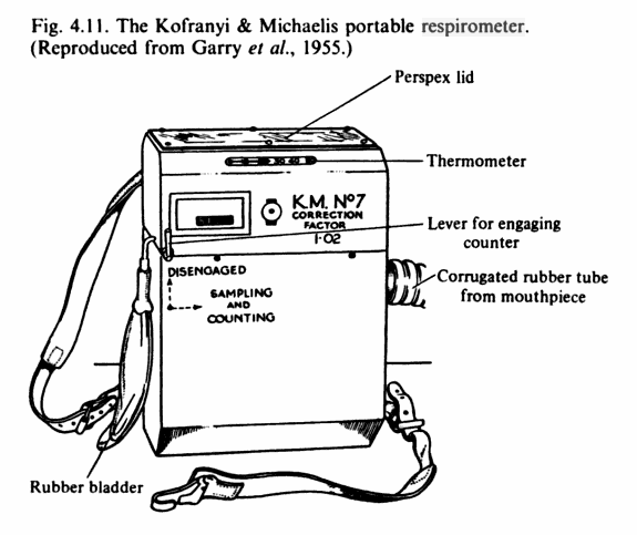
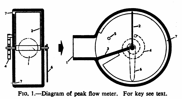
“The principle of operation of the instrument if illustrated diagrammatically in Fig. 1.  A cylindrical cavity about 5 in. (12.7 cm) is diameter and 1 3/8 in. (3.6 cm) deep has a radial inlet nozzle (1), and contains a movable vane (2) pivoted in the centre of the cylinder and fitted closely without touching. A fixed partition (3) extends from one side of the inlet orifice to within a short distance of the boss of the vane, but again does not touch it. A spiral spring (4) attached to one end of the spindle of the vane tends to rotate it towards the inlet orifice, a stop (5) preventing it from passing the orifice. A pointer (6) on the other end of the spindle indicates the position of the vane on a dial (not shown) and also serves to counterbalance it. An annular orifice (7) extends from round the periphery of the cylinder at the back, from one side of the inlet orifice to the other.

“It can be seen that when air is blown into the instrument it cannot escape (except for a small amount which leaks past the vane_ until the van has moved and uncovered part of the annular orifice. When the aria of the orifice uncovered is such that the pressure behind the vane is just sufficient to balance the force of the spring the vane will come to rest in a position which will depend on the flow rate. Since for a given pressure the rate of flow is proportional to the area of the orifice, the deflection of the vane would be proportional to the air flow if the tension of the spring were constant. In practice, the tension of the spring increases with the deflection so the that deflection is proportionally less at high flows than at low.  This has the effect of increasing the range of the instrument without loss of sensitivity at the lower end of the range, so that flows from 50 to 1,000 l./min can be covered in one instrument.

“The instrument is fitted with a ratchet which holds the vane and pointer in the position of maximum deflection. They can be returned to zero by pressing a release button.”

Spirometer for Calf BMR, 1951, Diagram

Spirometer_Calf_BMR_1951_Diagram

Handmade spirometer for measuring BMR.  From: Nutrition of the young Ayrshire Calf by KL Blaxter and A Howells, 1951, Volume 25, page 27.

“Fig. 1 shows an elevation of the spirometer from which the general dimensions can be obtained and Pl.1 shows the instrument with mask and rubber-tubing connexions attached. The base consists of an angle-iron and wood frame which can be levelled by means of levelling screws (H) at each corner. The frame (N) carrying the pulleys (G) is also constructed of angle iron, and, for added rigidity, is stayed to the top of the outer wall of the galvanized iron tank. The main assembly consists of a special water tank and light bell. The former is made of two tanks, the inner one being closed at the top and completely sealed. This allows a free water space of 2 in. between the walls of the inner and outer tank in which the bell is free to rise or fall. The main tanks are constructed of 20 s.w.g. iron and were galvanized after assembly to prevent rust. Two 1 in. bore pipes pass through the top of the inner tank and can be connected to low resistance taps (A, B) of 1 in. bore to one-way valves and a face mask. These pipes are fitted with drainage cocks (L) at their lowest level since water vapour from the air expired by the animals tends to condense in them. The bell (C) is constructed of 18 s.w.g. aluminum sheeting and is lightly wired at the base to endure rigidity. The bell is suspended by a thin cord which passes over two pulleys (G) mounted on ball races and is attached to the top of a brass tube (M) screwed into the centre of the top of the bell. This tube acts as a guard for the thermometer and is, of course, air tight.

“The correct counterpoising of the spirometer bell presented some difficulties since in such a large instrument it was not practicable to adopt the usual principle of concentric pulleys to compensate for the apparent decrease in the weight of the ball when immersed. Nor was it possible to use a heavy chain instead of a light cord to compensate for this decrease in weight. A modification of the rigid automatic siphon tube of Tissot’s (1904) original instrument was therefore devised. This consisted of a flexible leveling device and had proved extremely successful. The counterpoise weight (F) was made from a copper tube and a glass tube, the internal cross-sectional area of which was calculated to be equivalent to the cross-sectional area of the aluminum metal of the bell multiplied by its specific gravity. When the bell rises 1 cm. sufficient water is automatically siphoned by a rubber tube (K) attached to the tank into the counterpoise weight to compensate for the apparent increase in the weight of the bell.  The level of water is maintained constant in the tank by means of a constant overflow device (D) which is started at the commencement of a determination. The water level in the glass limb of the counterpoise weight is used to measure the gas volume, displacement of the counterpoise being exactly equivalent to the displacement of the bell.  The success of this method is shown by the absence of resistance to the respiration of the animal however much expired air has been accumulated in the bell. There is a small inertia attached to the instrument but this is a negligible factor compared with the resistance of the one-way flutter valves which are employed.  A maximum of 220 l. of expired air may be collected in the bell.”

Integrating Motor Pneumotachograph, 1958

Integrating_Motor_Pneumotachograph_1958

From New Scientist, November 29, 1956, page 21.

“…it will be necessary to measure their bodily energy exchanges; and this can be done with a modern apparatus called the IMP (integrating motor pneumotachograph).  This consists of a light air pump and flowmeter housed in a plastic box, which connects on one side with a mask fitted over the face and on the other with a sample-collecting unit packed in a bag worn on the back. The IMP measures, over a given time, the total volume of air breathed out by its wearer, and from this expired air it automatically takes representative (or integrated) samples.  The whole apparatus is so light, well-fitted and comfortable that it can be worn easily during violent exercise or peaceful sleep.

“The IMP was designed by Mr. H.S. Wolff, of the Human Physiology Division of the National Institute for Medical Research, to enable physiologists to study human energy exchanges under conditions ranging from swimming the Channel to bathing a baby. It has attachments allowing the wearer to drink through a tube or blow a whistle; though as yet the IMP cannot measure man’s energry exchanges while he is chatting, smoking, shaving or eating. It is manufactured by J. Langham Thompson.”