Many years ago I used to think that lung volume measurements were the easy part of PFTs. As time has gone on I’ve seen that getting accurate lung volume measurements is actually more difficult than getting accurate spirometry and DLCO results mostly because the errors tend to be subtle.
The errors that occur in lung volume measurements tend to cause an overestimation of lung volumes. This often means that restrictive diseases can be unrecognized or that hyperinflation and gas trapping can be diagnosed where it does not exist.
I see questionable lung volume test results more often than I’d like even from experienced technicians. When I find what went wrong I try to use these as “teachable moments” for all the the lab staff. Despite this the number of questionable test results never seems to drop below a certain level. I’d much prefer the error level was zero but since this is a situation that involves humans making measurements on humans I am likely being overly optimistic. A more realistic goal is to ask that the testing systems be smarter.
For at least the last 30 years there has been a industry-wide movement towards more automation in testing. The last time that I remember when you could buy a pulmonary function testing system that did not require a computer was the early 1980’s. This upside of this is that I can test a lot more patients more accurately and in less time with computer assistance than I could without it. The downside is that too many people believe that results are accurate because “that’s what the computer said”.
One of the most powerful aspects of computer software is that it can leverage expertise. Despite the dominence of computerized pulmonary function testing however, I have seen little increase in expertise. Routine testing errors that I first saw in computerized systems well over 20 years ago are still present. Here are two examples:
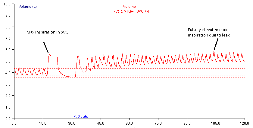
The procedure for the nitrogen washout test is for the patient to breath tidally for a period and then perform a slow vital capacity (SVC) maneuver. At maximal exhalation (RV) valves in the patient manifold are triggered, switching the patient to 100% oxygen as they resume tidal breathing. When the exhaled nitrogen level reaches a certain minimum level the test is completed. Here, there is a patient leak during testing and the post-SVC tidal breathing volume drifts upwards. When the computer analyzes the test results it overlooks two significant errors. First, it fails to recognize that the drift in the post-SVC tidal breathing indicates a leak which causes RV to be overestimated. Second, instead of measuring the maximal inspiration from where the SVC was performed, it takes it from the maximum of the post-SVC tidal breathing which causes SVC to be overestimated. Since TLC = RV+SVC, TLC is then markedly overestimated.
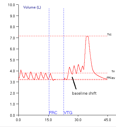
The procedure for plethysmography is for the patient to breath tidally for a period. This period is used to determine the volume level of the patient’s FRC. At end-exhalation a shutter interrupter closes (optimally at FRC) and the patient pants for a short period of time. While the shutter is closed the patient’s mouth pressure and the plethysmograph’s box pressure are measured and used to compute thoracic gas volume (TGV). When the shutter opens, the patient resumes tidal breathing and then performs a slow vital capacity maneuver. When the computer analyzes this test, it fails to recognize that the patient leaked while the shutter was closed which in turn caused the volume baseline for the SVC test to shift upwards. This causes the Inspiratory Capacity (IC) to be overestimated and since TLC = FRC+IC and RV = TLC – SVC, both TLC and RV are overestimated.
I have mixed feelings about calling for the manufacturers of test equipment to make their test systems smarter because I believe that technicians have a responsibility to understand the limitations of the equipment and the tests they perform. But since test equipment has become quite complicated and even trained and experienced technicians let these kind of errors pass through to a report, then it is evident that smarter software that at least warns that certain errors may be occurring would be helpful.

PFT Blog by Richard Johnston is licensed under a Creative Commons Attribution-NonCommercial 4.0 International License.


HI,
I was cross checking one of our more experienced techs today on a hispanic 9 year old male. I immediately noticed a large negative % predicted value for RV. After opening the test, I noticed all of the plethysmography loops tight but leaning to the left than typically to the right (deeper right for obstructive process and more vertical for restrictive processes on our software: Care Fusion VMAX). Do you have an explanation of the loop position change? It was at the end of the shift after a very busy day. I didn’t have time to further investigate and set the test aside until monday for further review. Insight would be greatly appreciated and would help with my investigation before I bring this child back for a test redo.
Robert –
A negative RV has to mean the FRC (TGV) was significantly underestimated. Most plethysmograph systems place box pressure on the X-axis and mouth pressure on the Y-axis. A steeper (more vertical) loop therefore indicates a lower change in box pressure in relation to mouth pressure and under normal circumstances a smaller lung volume. In this case it more likely means that the box pressure is being underestimated. Since the zero offset and gain of the box transducer usually doesn’t change abruptly my first guess would be a leak around the door (something caught in the door seal perhaps) but in my lab’s systems (NSpire) when this happens the loops become much more open (more oval, less like a line). Next, there is a connection somewhere inside the plethysmograph to the box transducer and I would check to see if something is blocking this. Finally, it is remotely possible the box transducer has failed so the next time you calibrate the box I’d check the readings on box pressure zero offset and gain then compare them to the last couple of weeks of calibrations to see if there has been a significant shift in either of these (although an increase in gain over time could also mean a progressive door seal failure). I don’t see any particular way the mouth pressure could suddenly be overestimated (the other cause of a steeper loop) but it is also remotely possible the mouth pressure transducer has failed, so I would re-check its calibration as well. Whether or not you find anything, I’d perform biological QC on the box to make sure it is working correctly before putting it back into service.
Good luck!
– Richard
Hello there!
I’m a new graduate, trying to figure out what it is exactly about nasal leaks that causes the baseline to drift upwards. My understanding of the issue so far is thus- the software we use (Breeze) selects an arbitrary point on the Y-axis of the time-volume plot in which to start charting flow. In my lab we are using flow sensors (bidirectional pitot tubes) to measure airflow- every time I have seen the above-mentioned artefact, the subject maintains their tidal volume (1L in, 1L out, over and over, as the trace shifts upwards). If the same volume is moving in and out, what about a nasal leak is causing the trace to drift upwards? Is it a thermal issue? I am trying to understand so that I can better troubleshoot.
Thanks!
Maddie –
If the subject has a noseclip on then it’s not very likely that they’re leaking through their nose unless it’s a difficult-to-fit nose. Other than that, the simple answer is that when it comes to breathing what goes in is not the same as what comes out.
Baseline drift is a potential problem for all flow-based test systems regardless of what technology they use. The most important cause is inhaled versus exhaled air temperature. Theoretically, it’s possible to mathematically correct for this but it requires knowing the exact temperature that air exits the lung and its exact temperature as it passes through the flow sensor and these two things are actually quite difficult to measure particularly since exhaled gas temperature changes throughout exhalation (see Temperature (in)correction for a discussion of this). The ATS/ERS standards say that spirometers should compensate for exhaled air temperature but do not give any particular guidelines on how this should be done. This leaves it up to the individual manufacturers to figure it out and each tends to apply its own “secret sauce” to the problem, with varying degrees of success.
There are also differences in gas density and viscosity between inhaled and exhaled air (which are due to changes in both composition and temperature) although these tend to have much less effect than temperature does. One other issue is that flow sensors, again regardless of which technology, are not perfectly linear, and this lack of linearity must be compensated for in the software (which occurs with varying degrees of success). I know that some manufacturer’s “cheat” by having their software reset the zero or end-exhalation point regularly during tidal breathing (again with varying degrees of success) so if you see a subject breathing on a flow-based system and the baseline doesn’t wander then it’s the software keeping it from doing this.
Volume-displacement spirometers are much less subject to tidal drift and this is largely because their mass acts as a sink for exhaled air temperature. They will still drift however, due to changes in gas composition since VO2 isn’t usually exactly the same as VCO2. There will be more drift if there is a CO2 absorbant in the breathing circuit (soda lime) which has to be compensated for by adding oxygen (and if you don’t absorb the CO2 then it’ll get uncomfortable to breathe pretty quickly).
Regards, Richard