Tag Archives: Palmer

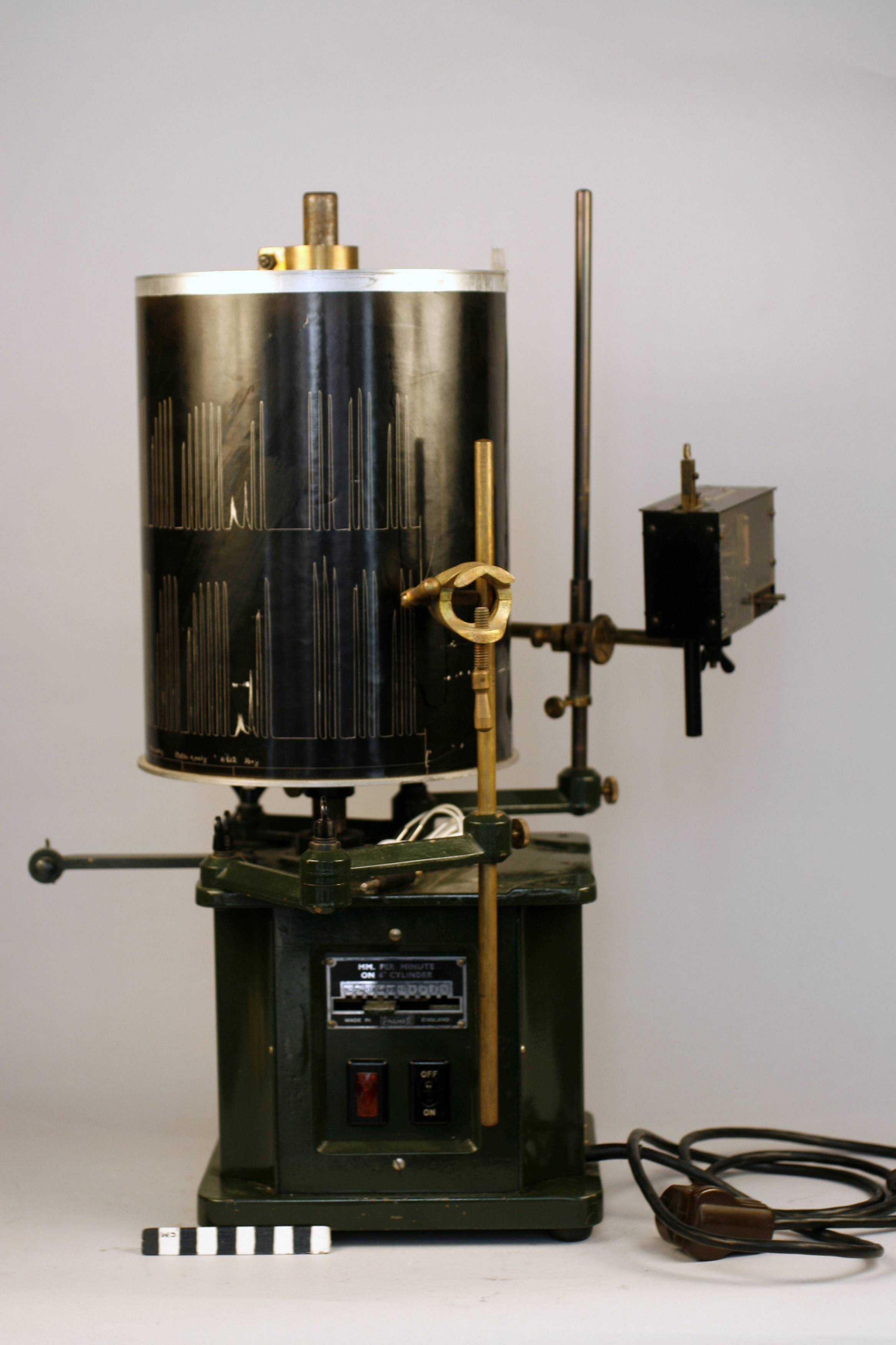
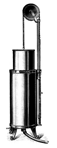
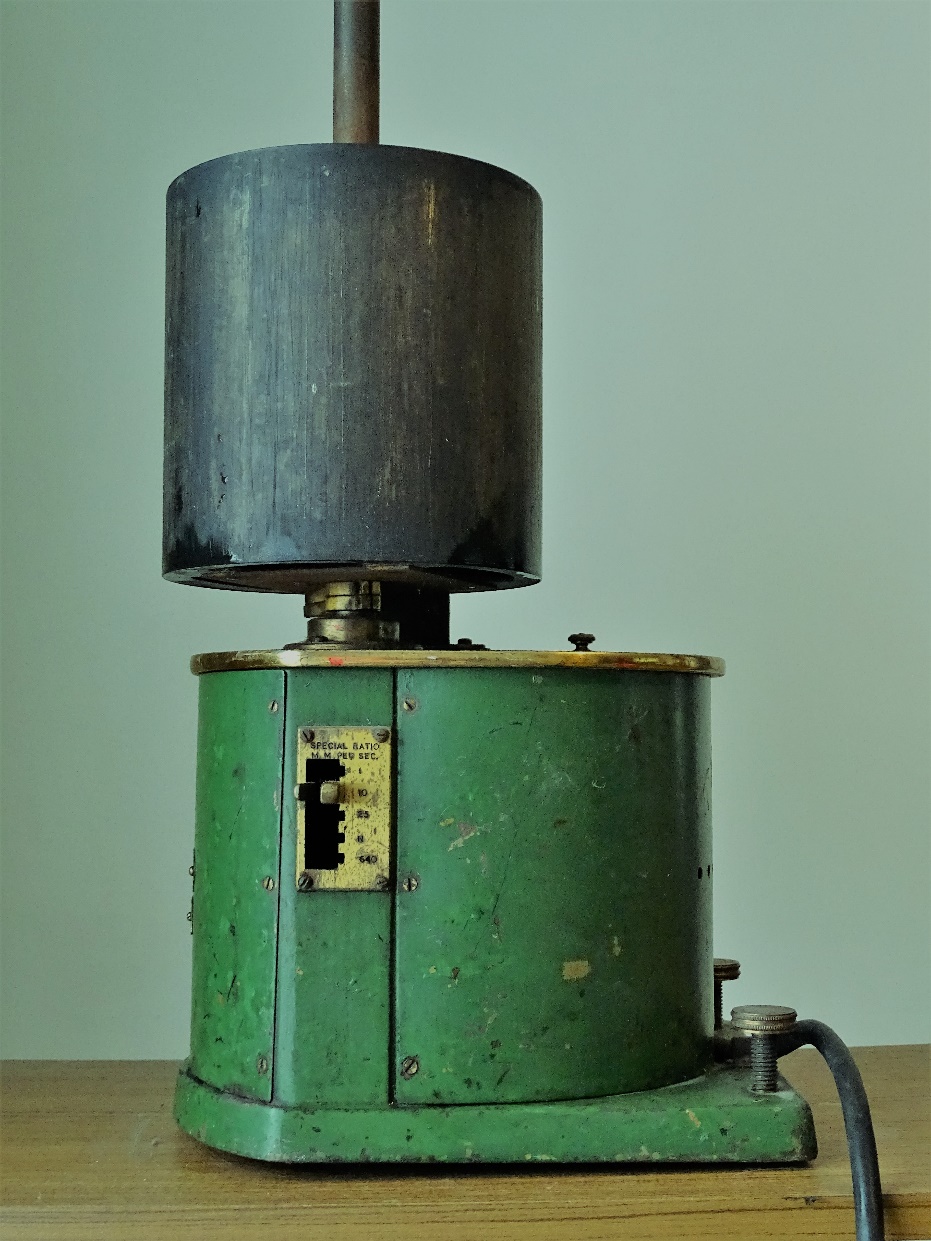
Kymograph, Sherrington Stirling Recording Drum, C. F. Palmer, circa 1955

Photo and description are kindly provided by Dr. David Chinn, for an upcoming ARTP article.

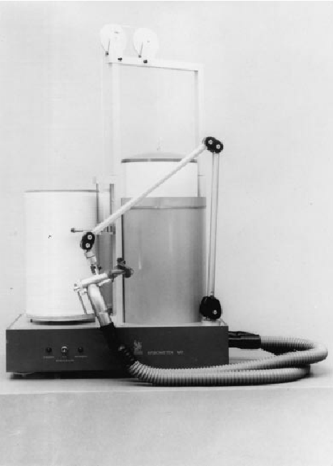
Sherrington Stirling Kymograph Recording Drum (C F Palmer (London) Ltd), c. 1955

A strip of paper the width of the drum is held above a smoking gas flame, the smoke from which settles on the paper to leave a surface of carbon soot. The smoked strip is wrapped around the drum and secured in place. The drum is set to run at a suitable speed (speeds available of 1, 10, 25, or 640 mm.s-1) and a stylus from a water spirometer (or other physiological recording device) is held against the strip. The recording is ‘scored’ into the carbon surface. Afterwards a calibration mark is applied and the strip is removed and passed through a ‘fixing fluid’ to create a permanent record that, after drying can be measured. It was a convenient way to record physiological signals but could be a very mucky job!”

Kymograph, Palmer, Circa 1930, Smoked-Drum

Kymograph_Palmer_circa_1930_Smoked_Drum

Found on the Steno Museum Collections website.  Although this kymograph was used to measure the effect of medications on muscle contraction it is much the same as the smoked-drum kymographs used on spirometers during the late 1800’s and early 1900’s. This was manufactured by Palmer of England, probably in the 1920’s or 1930’s.

“The black drum is prepared as follows:  A piece of strong, glossy graph paper tightened on the drum. The drum is rotated through a strong sooty flame (gas bubbled through toluene). During the experiment the sooty drum rotates a predetermined speed which is selected on the kymograph gear. After trying out the sooty paper is carefully removed from the drum and fixed with dammar resin dissolved in gasoline.”

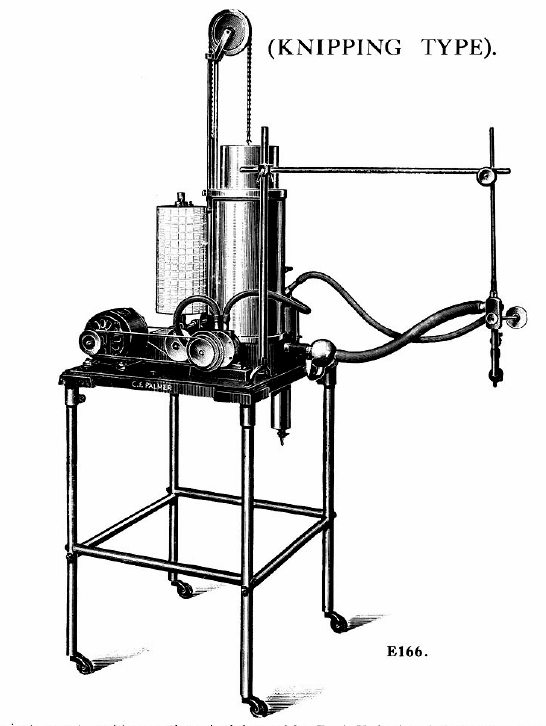
Spirometer, Palmer, 1934, Knipping Type Closed Circuit Respiration Apparatus

Spirometer_Palmer_1934_Knipping_Closed_Circuit

From Palmer, C. F. 1934. Palmer Research and Students’ Apparatus for Physiology, Pharmacology, Psychology, Bacteriology, Phonetics, Botany, etc.: Manufactured by C. F. Palmer (London) Ltd., Myographic Works, 63a, Effra Road, Brixton, London, S.W. 2. England, page 87.

“With this instrument working on the principle used by Prof. Knipping, it is possible to show on the same record, in addition to the volume of oxygen consumed, the volume of C.O2 produced.

“Also by using a rotary air pump to ventilate the apparatus, no valves are necessary.

“Dimensions and features of the spirometer itself and the recording cylinder are identical to those given for No. E150.

“The air circulating pump is substantially made and fitted with a water jacket for cooling; this should be connected to the nearest water supply. Lubricating points in the pump are conveniently placed, and should receive occasional attention.

“The electric motor is quiet running, and has ample power. Two model of this spirometer are made. In one, No. E165, the recording cylinder is driven by a clockwork movement making one revolution in 20 minutes.  In the other, No. E166, the recording cylinder is driven from the motor, this enables a two-speed gear to be used, so the the cylinder can be run at a faster rate (1 revolution in 2 minutes) in addition to the normal speed of one revolution in 20 minutes.”

Spirometer, Palmer, 1934, Knipping Type Closed Circuit Respiration Apparatus, Diagram

Spirometer_Palmer_1934_Knipping_Closed_Circuit_Diagram

From Palmer, C. F. 1934. Palmer Research and Students’ Apparatus for Physiology, Pharmacology, Psychology, Bacteriology, Phonetics, Botany, etc.: Manufactured by C. F. Palmer (London) Ltd., Myographic Works, 63a, Effra Road, Brixton, London, S.W. 2. England, page 88.

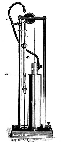
“The several parts of the assembly as shown in the outline drawing herewith, consist of the following: —

“1. The Spirometer A, the float of which is carefully balanced by a chain comensated counterpoise.

“2. The rotary air pump P, works on the centrifugal principle, and is driven by the electric motor M.

“3. The glas flask F contains the K.O.H. solution in the bottom, depending into this is a tube with a perforated bulb at one end, so that air from the pump is forced through the solution and to the outlet in the side. At the top of the flask is a container for the H2SO4, which is released through the cock C, when it is desired to ascertain the C.O2 produced.

“4. The three-way cock T.C. is used to connect the subject at the mouthpiece H, to the apparatus, or to the outside air O.

“5. The “U” tube S.V. containing water, acts as a safety valve in the circuit.

“6. The recording cylinder D carries the calibrated record charts W being the ink writing pen.

“Very briefly the circulation system is as follows: Gas is from from the Spirometer A, which has previously been charged with oxygen, into the Pump P, and foced from there down the centre tube of the flask F, and through the K.O.H. where the C.O2 produced is absorbed, and so to the three-way cock T.C, and the mouthpiece H, from thence it returns through the safety valve S.V. to the Spirometer A.  The reduction in volume due to the amount of oxygen consumed, is registered by the ink pen W, on the calibrated chart affixed to the recording cylinder D.

“On order to ascertain the amount of C.O2 produced, the subject at the mouthpiece H should be disconnected from the apparatus by the three-way cock TC, the air should continue to be circulated in the apparatus until the pen W records a horizontal line. The H2SO4 is then run slowly into the K.O.H in the flask F, through the cock C.  Cooling is effected by the water in a cylindrical tank around the outside of the flask.

“The action of the H2SO4 on the K.O.H. causes the C.O2 absorbed to be given off, and so the float of the Spirometer rises, the amount being recorded by the ink pen W.

“The foregoing is only a very simple description of the method of using the apparatus; before actual records are taken with subjects, further information should be obtained from a competent authority.”
Spirometer, Palmer, 1934

Spirometer_Palmer_1934_with_syphon_counterpoise

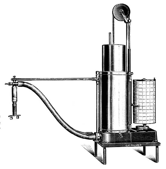
Palmer spirometer with syphon counterpoise.  Found in Palmer, C. F. 1934. Palmer Research and Students’ Apparatus for Physiology, Pharmacology, Psychology, Bacteriology, Phonetics, Botany, etc.: Manufactured by C. F. Palmer (London) Ltd., Myographic Works, 63a, Effra Road, Brixton, London, S.W. 2. England, page 54.

“This illustration shows a spirometer, embodying the Syphon Counterpoise principle devised by Tissot, arranged for use in the Bio-chemistry Department of the Middlesex Hospital.

“A light float B is connected by a cord over the pulleys C to the Counterpoise D, which slide on guide wires; a  Syphon runs from the main water tank A, through tubes E, G and F into the Counterpoise D.  It therefore follows, that as the float B, is raised the Counterpoise D falls, and water is syphoned from A into D until it is level in both, this having effect of making the Counterpoise D weigh heavier the greater the distance float B is out of the water. By carefully determining the bore and weight of the Counterpoise in relation to the float, an almost exact balance can be obtrained for the full movement of the Float.”