Brodie Bellows, 1902

Brodie_Bellows_1902

T.G. Brodie developed the recording bellows to measure small changes in volume and were intended to be a more accurate replacement for Marey’s tambour. They were intended for research with small animals and there were four sizes: 30×20 mm with a volume of 7.5 cc; 45 x 30 mm with a volume of 25 cc, 60 x 40 mm with a volume of 67 cc and 120 x 80 cc with a volume of 500 cc.

From Brodie, Thomas Gregor. “On recording variations in volume by air-transmission. A new form of volume-recorder.” The Journal of Physiology 27.6 (1902): 473-487.

Brodie Bellows, 1913

Spirometer_Brodie_Bellows_1913

Intended for experiments with small animals or in venous occlusion plethysmography, the bellows are approximately 3 cm long.  It was usually referred to as a recording tambour.

Found in A Text-book of Pharmacology and Some Allied Sciences: (therapeutics, Materia Medica, Pharmacy, Prescription-writing, Toxicology, Etc.), Together with Outlines for Laboratory Work; Solubility and Dose Tables, Etc, by Torald Hermann Sollman, published by W.B. Saunders, 1913, page 815.

“Recording Tambours: The cheapest form consists of a home-made organ-bellow (fig. 113), the sides of very thin leather or gold-beaters skin. A 3 or 4 cm Marey’s tambour answers well.  The 3 cm Brodie Bellows (Made by C.F. Palmer, 6 Upper Tulso Hill, London, N.W.) is the most delicate.  All bear a straw and a writing point about 6 inches long.”

Spirometer, Burt’s, 1876

Spirometer_Burt_1876

From Patent #180842, filed August 1876 by W.H. Burt.

“My invention is designed to produce a pocket spirometer, by which the breathing-capacity of a persons lungs can readily be measured in cubic inches, by mercury, oil, glycerine, spirits, water, or all other liquid substances. It consists of a simple glass tube with a small bulb at the base lilled with mercury or other liquid, upon which bulb is a rubber tube with a mouth-piece; also, a vertical scaled tube, into which the mercury or other liquid is blown for testing the lungs in cubic inches.

“The drawing is partly a side elevation and partly a sectional elevation of my improved spirometer.

“A is the glass bulb, for containing the mercury or other liquid substance. B is the rubber tube, with a mouth-piece, O, and D is the scaled tube for measuring the height of the column raised by the lungs. The rubber tube connects with a nozzle on the top of the bulb, and the glass tube connects with the bottom of the bulb by a return bend. The top of the vertical tube is open to the atmosphere, to prevent compressing the air above the liquid, and a little cap, E, may be used for closing it, to exclude dust, &c., and preventing the liquid from running out by pneumatic pressure. This cap must be taken off when in use. Or, the top of the scaled tube and mouth-piece may have a funnel-shaped glass blown into the top of each, which will prevent the liquid from running out, and the cap can be dispensed with; or a cork may be put into the nozzle, and also in the tube, to retain the liquid, in which case both the cap and funnel-shaped glass will not be required. When in use, this cork must be removed, or the instrument will not work.”

This spirometer appears to have been manufactured and sold because it was reviewed by Eldridge C. Price, MD in the 1884 issue of Medical Times (Volume 12, page 40):

“Burt’s instrument requires a maximum amount of muscular strength, and in the haemmhorragic diathesis its use is dangerous. In fact the instrument is nothing but a modified manometer, and is no index of lung capacity. I have seen the worthlessness of this instrument as a spirometer illustrated, when a well-muscled man of 5 feet 7 inches of height, who at one sudden and powerful expiration forced the mercury above the 300 cubic inch index, a few grains even shooting out of the tube.  This gentleman’s actual respiratory capacity by future accurate mensuration proved to be 248 cubic inches.”

Spirometer, Palmer, 1934, Knipping Type Closed Circuit Respiration Apparatus

Spirometer_Palmer_1934_Knipping_Closed_Circuit

From Palmer, C. F. 1934. Palmer Research and Students’ Apparatus for Physiology, Pharmacology, Psychology, Bacteriology, Phonetics, Botany, etc.: Manufactured by C. F. Palmer (London) Ltd., Myographic Works, 63a, Effra Road, Brixton, London, S.W. 2. England, page 87.

“With this instrument working on the principle used by Prof. Knipping, it is possible to show on the same record, in addition to the volume of oxygen consumed, the volume of C.O2 produced.

“Also by using a rotary air pump to ventilate the apparatus, no valves are necessary.

“Dimensions and features of the spirometer itself and the recording cylinder are identical to those given for No. E150.

“The air circulating pump is substantially made and fitted with a water jacket for cooling; this should be connected to the nearest water supply. Lubricating points in the pump are conveniently placed, and should receive occasional attention.

“The electric motor is quiet running, and has ample power. Two model of this spirometer are made. In one, No. E165, the recording cylinder is driven by a clockwork movement making one revolution in 20 minutes.  In the other, No. E166, the recording cylinder is driven from the motor, this enables a two-speed gear to be used, so the the cylinder can be run at a faster rate (1 revolution in 2 minutes) in addition to the normal speed of one revolution in 20 minutes.”

Spirometer, Palmer, 1934, Knipping Type Closed Circuit Respiration Apparatus, Diagram

Spirometer_Palmer_1934_Knipping_Closed_Circuit_Diagram

From Palmer, C. F. 1934. Palmer Research and Students’ Apparatus for Physiology, Pharmacology, Psychology, Bacteriology, Phonetics, Botany, etc.: Manufactured by C. F. Palmer (London) Ltd., Myographic Works, 63a, Effra Road, Brixton, London, S.W. 2. England, page 88.

“The several parts of the assembly as shown in the outline drawing herewith, consist of the following: —

“1. The Spirometer A, the float of which is carefully balanced by a chain comensated counterpoise.

“2. The rotary air pump P, works on the centrifugal principle, and is driven by the electric motor M.

“3. The glas flask F contains the K.O.H. solution in the bottom, depending into this is a tube with a perforated bulb at one end, so that air from the pump is forced through the solution and to the outlet in the side. At the top of the flask is a container for the H2SO4, which is released through the cock C, when it is desired to ascertain the C.O2 produced.

“4. The three-way cock T.C. is used to connect the subject at the mouthpiece H, to the apparatus, or to the outside air O.

“5. The “U” tube S.V. containing water, acts as a safety valve in the circuit.

“6. The recording cylinder D carries the calibrated record charts W being the ink writing pen.

“Very briefly the circulation system is as follows: Gas is from from the Spirometer A, which has previously been charged with oxygen, into the Pump P, and foced from there down the centre tube of the flask F, and through the K.O.H. where the C.O2 produced is absorbed, and so to the three-way cock T.C, and the mouthpiece H, from thence it returns through the safety valve S.V. to the Spirometer A.  The reduction in volume due to the amount of oxygen consumed, is registered by the ink pen W, on the calibrated chart affixed to the recording cylinder D.

“On order to ascertain the amount of C.O2 produced, the subject at the mouthpiece H should be disconnected from the apparatus by the three-way cock TC, the air should continue to be circulated in the apparatus until the pen W records a horizontal line. The H2SO4 is then run slowly into the K.O.H in the flask F, through the cock C.  Cooling is effected by the water in a cylindrical tank around the outside of the flask.

“The action of the H2SO4 on the K.O.H. causes the C.O2 absorbed to be given off, and so the float of the Spirometer rises, the amount being recorded by the ink pen W.

“The foregoing is only a very simple description of the method of using the apparatus; before actual records are taken with subjects, further information should be obtained from a competent authority.”

Spirometer, Palmer, 1934

Spirometer_Palmer_1934_with_syphon_counterpoise

Palmer spirometer with syphon counterpoise.  Found in Palmer, C. F. 1934. Palmer Research and Students’ Apparatus for Physiology, Pharmacology, Psychology, Bacteriology, Phonetics, Botany, etc.: Manufactured by C. F. Palmer (London) Ltd., Myographic Works, 63a, Effra Road, Brixton, London, S.W. 2. England, page 54.

“This illustration shows a spirometer, embodying the Syphon Counterpoise principle devised by Tissot, arranged for use in the Bio-chemistry Department of the Middlesex Hospital.

“A light float B is connected by a cord over the pulleys C to the Counterpoise D, which slide on guide wires; a  Syphon runs from the main water tank A, through tubes E, G and F into the Counterpoise D.  It therefore follows, that as the float B, is raised the Counterpoise D falls, and water is syphoned from A into D until it is level in both, this having effect of making the Counterpoise D weigh heavier the greater the distance float B is out of the water. By carefully determining the bore and weight of the Counterpoise in relation to the float, an almost exact balance can be obtrained for the full movement of the Float.”

Spirometer, Mitchell’s, 1859

Spirometer_Mitchell_1859

From The American Journal of Medicine, 1859, page 379.

“1859, Jan. 5. Improved Spirometer – Dr. S. W. Mitchell exhibited an improved form of spirometer, of which he gave the following description: –

“While conducting some recent researches upon the physical statistics of natives of this country, I was struck with the clumsiness, and, in some cases, with the inaccuracy, of the form of spirometer in common use.  This instrument, well known as Hutchinson’s spirometer, is accurate in its indications when well made, but is always inconvenient, because it requires to be filled with water, and, on account of its weight and form, is not easily carried from place to place. This latter objection applies equally to all the spirometers I have examined; while most of the instruments on the side of the water are also open to the additional objection of want of accuracy.

“The instrument which I have used in its place is merely a small “dry gasmeter” numbers of which are made in this city by Messrs. Code, Hopper & Co.  With the aid of Mr. Gratz, a member of this firm, some slight alterations have been made in the valves of the meter, and the inlet-pipe was somewhat narrowed. A large dial-plate, graduated to inches and halves of inches, was placed on top of the meter, so that the rotation of an indicating hand would mark the number of cubic inches which passed through the machine.

“It is unnecessary to describe the interior details of the meter thus adapted to spirometric use. In the form of a dry gas-meter it has been used, almost to the exclusion of the very inconvenient “wet-meter” in many parts of this country, and has been found to perform its work of registration, for years together, without serious error and without needing repairs.

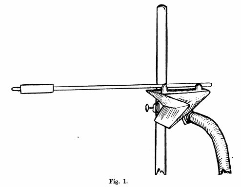
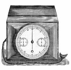
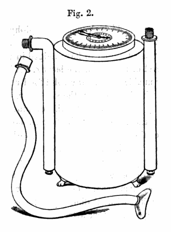
“The instrument thus briefly described is figured in the annexed cut. Its height as but fourteen inches, its width eleven. The inlet-pipe is so marked, and to this, when arranged for use, an India-rubber tube and mouthpiece are attached. The inlet and outlet-pipes form convenient handles when the spirometer is to be carried.

“I have tested the accuracy of this little instrument with great care, and have put to more severe trials than the meter is usually subjected to. Its indications appeared to be to be almost perfect. The new form of spirometer runs with so little friction, that a pressure of one-eighth of an inch of water will move it readily. One source of error is thus avoided, since, if the instrument did not move so easily the first air blown into it would be more or less condensed, and so occupy less space than it should do.

“After the spirometer has been used fifty or sixty times, the moisture from breath, which collects in the form of a few drops of water within the instrument, should be allowed to escape by the removal of a button placed underneath the meter.

“The form of spirometer here described has lately been employed by the biological department of the Academy of Natural Sciences of this city, to measure the pulmonary capacity of some five hundred men. In every way the instrument was found to be satisfactory,being portable, requiring no water, and not being readily deranged.

“So far as the committee have gone, hey have seen increasing reason to regard with distrust all spirometric valuations of men. In every case they have been careful, by repeated trials, to obtain the best result of which the individual was capable; but the have been, so far, much impressed with the difference between their own results and those obtained buy others abroad. As the height, weight and girth of chest have also been taken, the committee hope, at some future time, to be able to report in detail their results, as bearing upon the lung capacity of men born in this country.

“The spirometer is to be obtained from Messrs. Code & Hopper of this city, well known as manufacturers of gas-meters. The cost of the new instrument will probably not exceed fifteen dollars, which is less than that of the worst ordinary spirometer now in use.”