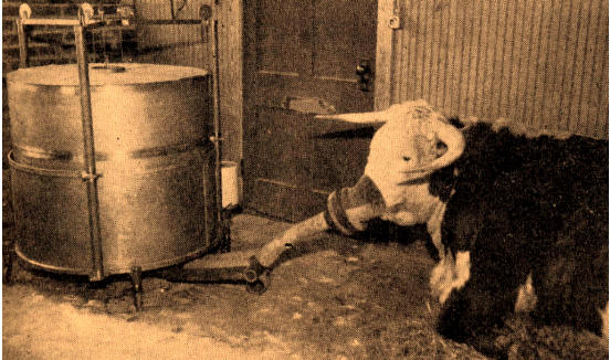
Found at the webpage for the Brody Environmental Center. Credited to “Bioenergetics and Growth” by Samuel Brody, 1945.
Found at the webpage for the Brody Environmental Center. Credited to “Bioenergetics and Growth” by Samuel Brody, 1945.
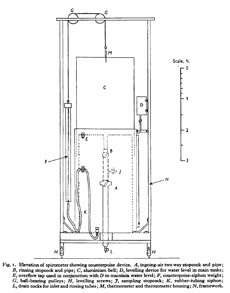
Handmade spirometer for measuring BMR. From: Nutrition of the young Ayrshire Calf by KL Blaxter and A Howells, 1951, Volume 25, page 27.
“Fig. 1 shows an elevation of the spirometer from which the general dimensions can be obtained and Pl.1 shows the instrument with mask and rubber-tubing connexions attached. The base consists of an angle-iron and wood frame which can be levelled by means of levelling screws (H) at each corner. The frame (N) carrying the pulleys (G) is also constructed of angle iron, and, for added rigidity, is stayed to the top of the outer wall of the galvanized iron tank. The main assembly consists of a special water tank and light bell. The former is made of two tanks, the inner one being closed at the top and completely sealed. This allows a free water space of 2 in. between the walls of the inner and outer tank in which the bell is free to rise or fall. The main tanks are constructed of 20 s.w.g. iron and were galvanized after assembly to prevent rust. Two 1 in. bore pipes pass through the top of the inner tank and can be connected to low resistance taps (A, B) of 1 in. bore to one-way valves and a face mask. These pipes are fitted with drainage cocks (L) at their lowest level since water vapour from the air expired by the animals tends to condense in them. The bell (C) is constructed of 18 s.w.g. aluminum sheeting and is lightly wired at the base to endure rigidity. The bell is suspended by a thin cord which passes over two pulleys (G) mounted on ball races and is attached to the top of a brass tube (M) screwed into the centre of the top of the bell. This tube acts as a guard for the thermometer and is, of course, air tight.
“The correct counterpoising of the spirometer bell presented some difficulties since in such a large instrument it was not practicable to adopt the usual principle of concentric pulleys to compensate for the apparent decrease in the weight of the ball when immersed. Nor was it possible to use a heavy chain instead of a light cord to compensate for this decrease in weight. A modification of the rigid automatic siphon tube of Tissot’s (1904) original instrument was therefore devised. This consisted of a flexible leveling device and had proved extremely successful. The counterpoise weight (F) was made from a copper tube and a glass tube, the internal cross-sectional area of which was calculated to be equivalent to the cross-sectional area of the aluminum metal of the bell multiplied by its specific gravity. When the bell rises 1 cm. sufficient water is automatically siphoned by a rubber tube (K) attached to the tank into the counterpoise weight to compensate for the apparent increase in the weight of the bell. The level of water is maintained constant in the tank by means of a constant overflow device (D) which is started at the commencement of a determination. The water level in the glass limb of the counterpoise weight is used to measure the gas volume, displacement of the counterpoise being exactly equivalent to the displacement of the bell. The success of this method is shown by the absence of resistance to the respiration of the animal however much expired air has been accumulated in the bell. There is a small inertia attached to the instrument but this is a negligible factor compared with the resistance of the one-way flutter valves which are employed. A maximum of 220 l. of expired air may be collected in the bell.”
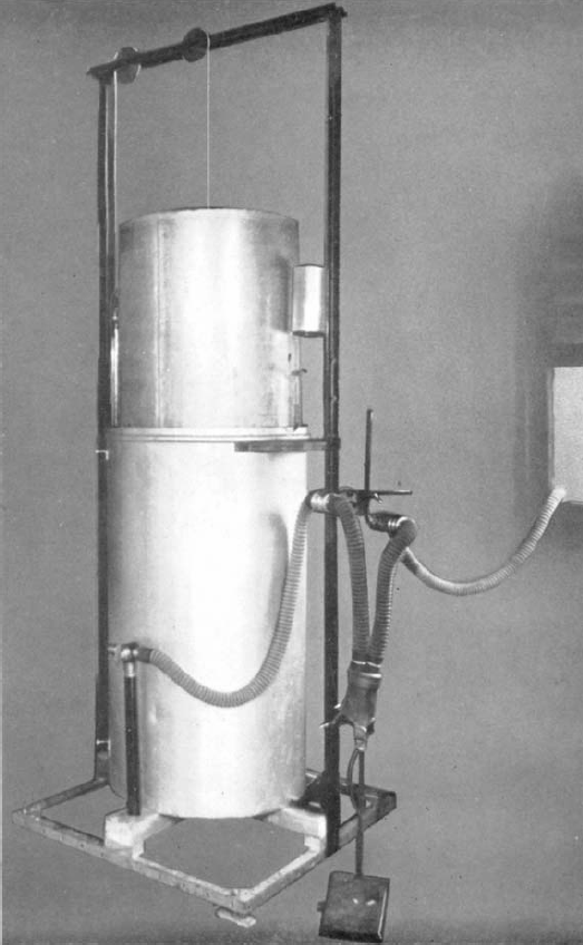
Handmade spirometer for measuring BMR. From: Nutrition of the young Ayrshire Calf by KL Blaxter and A Howells, 1951, Volume 25, plate I.

It’s price was $5.00. From Lewis’ New Gymnastics for Ladies, Gentlemen and Children and Boston Journal of Physical Culture, January 1861, Volume 1, Number 5, page 34.
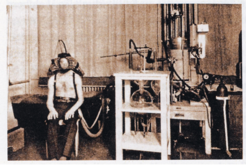
From Archives of Internal Medicine, Vol 28, page 849, 1921. Manufactured by G.F. Soderstrom.
Found at www.egms.de. Subject is wearing a special mask developed for exercise testing. Photo taken at the Sports University of Cologne, 1949. Spirometer is likely a closed-circuit Dargatz Knipping spirometer.
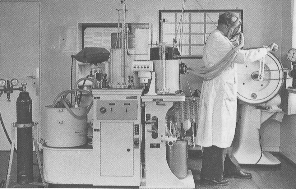
Photo found at esport.dshs-koeln.de. Exercise testing using a hand-cranked electrically braked ergometer. Spirometer is described as closed-circuit Knipping Model 210 D, manufactured by Dargatz, a German company.
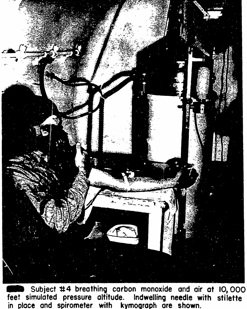
From: Hall AL, Patterson CA, Colehour JK. Safe human tolerance for high concentrations of CO over short periods of time. U.S. Naval School of Aviation Medicine, Pensacola, Florida, 1951. DTIC Document #622608.
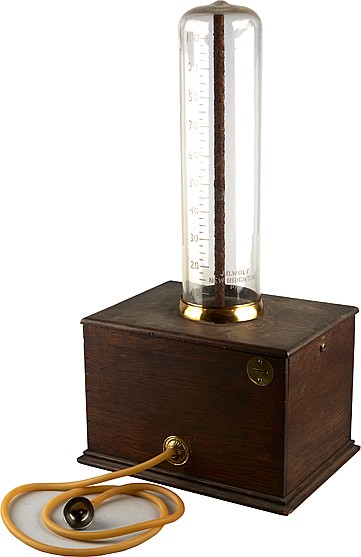
Coin-operated (1 cent) spirometer. Found on an auction listing on Invaluable.com.
A counter-weighted water-seal spirometer. Found at WellcomeLibrary.org. Used by Robert E C Altounyan (1922-1987) who contributed to the development of Intal. He used it to perform spirometry on himself during the 1960’s in England. Manufacturer unknown.