From: Manual of Medical Research Laboratory, United States School of Aviation Medicine, Randolph Field, Tex, United States. War Dept. Division of Military Aeronautics, U.S. Government Printing Office, 1918, page 214.
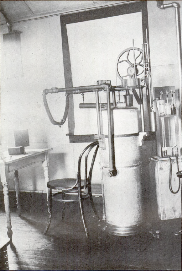
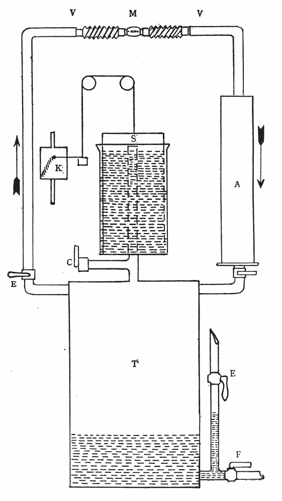
“The base of the machine is a steel tank (T) of 60 or 80 liters capacity, according to the type. Type A has 80-liter, and types B and C 60-liter tanks. Air is inspired from the tank through the pipe at the left, and is expired back into the tank through the pipe and absorbing cartridge (A) at the right. The valves (VV) keep the air stream flowing always in the proper direction. In order to maintain the contained air at approximately atmospheric pressure and to allow for changes in volume, a wet spirometer (S), carefully counterbalanced, is mounted on the tank and communicated freely with its interior through the vertical pipe (P). A stylus attached to the counterweight records the movements of the spirometer upon the smoked drum of the kymograph (K). Water is admitted to the tank through valve (E) to replace the volume of the used oxygen and also to flush out the tank after an experiment. The water is drained away to the sewer by means of valve (F). Valve (C) affords a free opening to the atmosphere for flushing the tank of the rebreathed air. Valve (D) should invariably be closed while flushing the tank, otherwise wate will enter the absorption chamber (A) and ruin the cartridge. The cartridge is a cylindrical paper tube filled with solid caustic soda, cast in thin shells so as to expose a large surface to the action of the gas. IT is prepared for use in the machine by punching the ends full of quarter inch holes with a pencil. The brass ring is then inserted in the lower end of the cartridge, the rubber ring fitted over the end, and the whole inserted into the absorption chamber. Cartridges should never be used without both rubber ring and brass ring in proper position. Valve parts may be removed from the air valves (VV) by means of the brass spanner wrench, which, together with two new valve parts are furnished with each machine. Counterweight slide rods should be frequently greased with vaseline and the pulleys oiled. In setting up a machine care should be taken to level it properly, so the the inner can of the spirometer hands freely in the outer can and does not rub against the side.”