From: Vital Capacity in Heart Disease, by HW Jones. British Medical Journal, May 12, 1928, page 795.
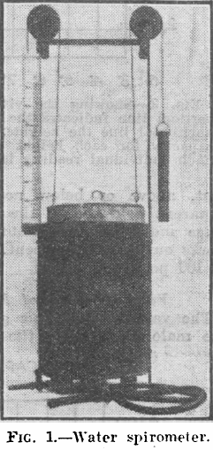
“In this investigation a simple water spirometer (Fig. 1) has been used, graduated in cubic centimeters and balanced so no effort is required to raise the cylinder. A large number of glass mouthpieces were provided, so that they could be readily disinfected between each patient without loss of time.
“It is always advisable to explain fully the working of the machine before actually taking the measurement, as it is necessary to get the patient’s whole-hearted cooperation to obtain an accurate result. Each patient was given three attempts, the highest being taken as the vital capacity. In taking the reading if there is any tendency to expire through the nose this should be closed by pinching during expiration. When patients were not confined to bed the record was always taken standing, and generally in their ordinary clothes. With regard to the patients who were confined to bed they were all able to sit up in bed when taking the reading , so that it was not necessary to correct the reading for the 5 percent diminuation in the vital capacity which has been shown by Christie and Beams and Rabinowitch to occur when the reading is taken in the recumbent position. Owing to the variability of the vital capacity according to the height, sex, age and race of the individual concerned, the simple reading of the number of cubic centimeters expired gives little indication of the deviation from normal, unless the reading is expressed in percentages of the standard vital capacity for that individual.”
From: A portable calorimeter for the determination of both oxygen and carbon dioxide. JF McClendon, GJ Humphrey, MM Loucks. Journal of Biological Chemistry, 1926; 69: 513-517.
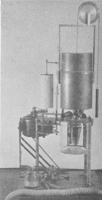
“The apparatus consists of a spirometer holding 6 liters and with a recording drum of such size that charts purchased from the Sanborn Corporation may be used to record the respirations. The bell is counterpoised by a chain and weight passing over a wheel on which the liters of oxygen in the bell may also be read if desired. Below the spirometer is a museum jar holding 6 liters in which is placed a standard solution of Ba(HO)2 containing BaCL2 to reduce hydrolysis and 0.1 gm. phenolphthalein, A synchronous alternating current electric motor drives a clock work revolving the recording drum and at the same time drives a centrifugal pump which sprays the Ba(HO)2 in the museum jar. The pump is made off a inverted, truncated hollow cone. The cone is open above and below and is provided with radial baffles or septa which allow passage of the fluid upwards but force the fluid to rotate with the cone. The rotation of the cone causes the fluid to be sucked up from the bottom and sprayed out at the top at a very rapid rate in order to absorb the CO2 out of the air.
“In the use of the apparatus a mask or mouthpiece is applied to the patient, having a 1 inch side outlet which allows free breathing to the outside until the moment of beginning the experiment. A 1-1/4 inch bore rubber tube leads to a brass tube of the same bore going down just below the level of the Ba(HO)2 solution in the museum jar, admitting expired air into the jar. The passage of the tube below the solution, acting as a valve, prevents reversal of the air current. From the museum jar a vertical tube rises up through the water in the spirometer. Another 1-1/4 inch brass tube comes down through the water of the spirometer and passes to the outside where it is connected with a valve and then to a 1-1/4 inch rubber tube to the mask over the patient’s face. This tube brings oxygen from the spirometer to the mask and the valve prevents reversal of the current. The apparatus is mounted on a stand of sufficient height to allow the museum jar to be raised up in place and clamped to the plate of the apparatus with six clamps, being made air-tight by a rubber gasket. In operation after the mask is applied (the bell having been filled with oxygen and the Ba(HO)2 solution having been introduced) the motor is started causing a base line to be written on the recording drum and the Ba(HO)2 rapidly sprayed in the museum jar. The patient is watched until the respirations become regular; then the side outlet to the mask is closed with a rubber stopper and the color of the Ba(HO)2 solution is carefully watched. As soon as the phenolphthalein is decolorized, the stopper to the side outlet of the mask is withdrawn, thus ending the experiment. The motor may be stopped and the mask removed at leisure.”
From: The response of cardio-vascular system to respiratory exertion. HF Frost, The Boston Medical and Surgical Journal, 1924, page 109.
“The apparatus finally decided upon consists of two elements: a vacuum-pressure Tycos guage and a Simplex spirometer. The gauge is necessarily delicate, registering positive and negative pressure in centimeters of mercury. It is manufactured by the Taylor Instruments Companies of Rochester, New York. The spirometer is of the “wind-wheel” type, the revolutions of the wheel registering on the dial the amount of air expired, in cubic inches. It is manufactured by Messrs. Roberts and Quinn, 401 Bridge Street, Brooklyn, New York. We recognize that this type of spirometer does not accurately register vital capacity. A certain amount of air is “lost” in overcoming the inertia of the mechanism at the beginning of respiration; while after respiration has ceased the wheel continues to revolve for a short period until its momentum has ceased. To a certain extent, the latter fault compensates for the former. This type, however, suits our purpose in that it is compact, gives a sufficiently accurate idea of the vital capacity and offers considerable resistance to forced expiration.”
From: The respiratory response to carbon dioxide. By HW Davies, GR Brow, CAL Binger. Journal of Experimental Medicine, 1925, page 38.
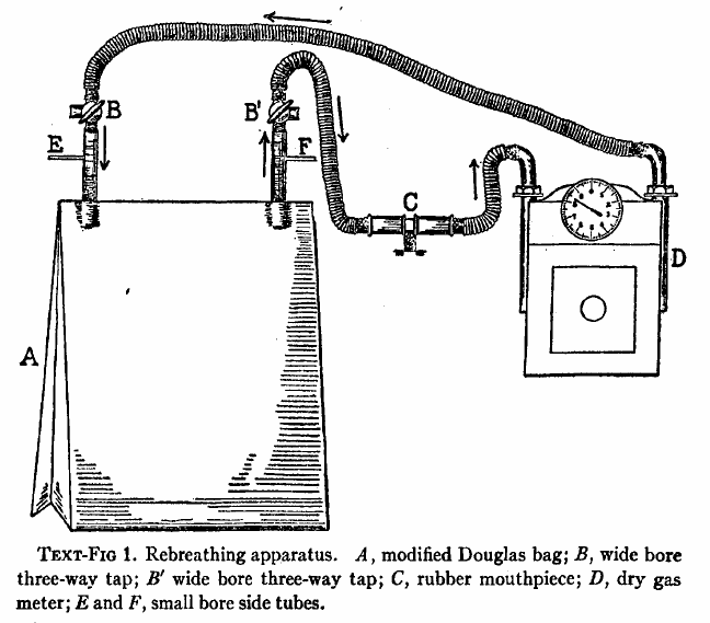
“The effect of gradually increasing percentages of carbon dioxide was studied by means of rebreathing in a closed circuit consisting of a modified Douglas Bag with inflow and outflow tubes, a dry meter, and a rubber mouthpiece fitted with inspiratory and expiratory valves. The general arrangement of the apparatus is shown semidiagrammatically in text-fig. 1. The direction of airflow is indicated by means of arrows. A is the modified Douglas Bag of 100 liters capacity. B, B’ are wide bored three-way taps. C is the mouthpiece. D is a twenty-light capacity “B-type” dry meter manufactured by D. MacDonald and company of Albany. The resistance of this meter is almost negligible even at the maximal rates of pulmonary ventilation produced by high percentages of carbon dioxide in the inspired air. E is a small bore side tube connected with an oxygen tank fitted with reducing valve and a flow meter calibrated with approximate accuracy rates of flow of less than 1 liter per minute. A similar side tube, F, is used to obtain samples of inspired air, either into exhausted sampling tubes or directly into the burette of the Haldane gas analysis apparatus. By way of the three-way stop cocks B,B’ the subject may be made to inhale from and exhale into the room air through the meter, and his normal respiratory rate and minute volume may be determined. When the stop-cocks are turned the apparatus becomes a closed circuit, inspiration and expiration being from and to the Douglas Bag, A.”
From: The assessment of physical fitness by correlation of vital capacity and and certain measurements of the body. By Georges Dreyer and George Fulford Hanson, 1921, page 9.
“The subject should be seated on a high stool with his back straight, opposite the spirometer, the dial being so placed that he cannot see the readings. This is done for the purpose of keeping him in ignorance of the readings while be examined, as it is found that any such knowledge tends to interfere with the accuracy of the results. The neck, chest and abdomen must be free from any obstruction to free movement, such as collar belt or stays. The subject is asked to fill the lungs to the maximum capacity, then the nose is held with one hand, the mouthpiece is placed well inside the lips with the other hand in such a manner as to prevent any escape of air round it. He now blows steadily into the tube, and empties the lungs as completely as possible into the spirometer, being encouraged during the last period of expiration to make the utmost effort to expel all air from the lungs. The readings are given in liters and decimals of liters, to be read directly from the dial. After each expiration the needle on the single liter dial should be brought back to zero by the observer. At the end of a long series of expirations the spirometer should be inverted, to allow any condensed moisture to escape. Five successive observations should be taken and recorded, the subject being allowed a short time for a short rest after each.”
From: The assessment of physical fitness by correlation of vital capacity and and certain measurements of the body. By Georges Dreyer and George Fulford Hanson, 1921, page 8.
From: CLXXII: An apparatus for the graphical recording of oxygen consumption and carbon dioxide output, especially adapted for clinical work. By H.C. Hagedorn. Biochemical Journal, 1924, page 1304.
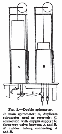
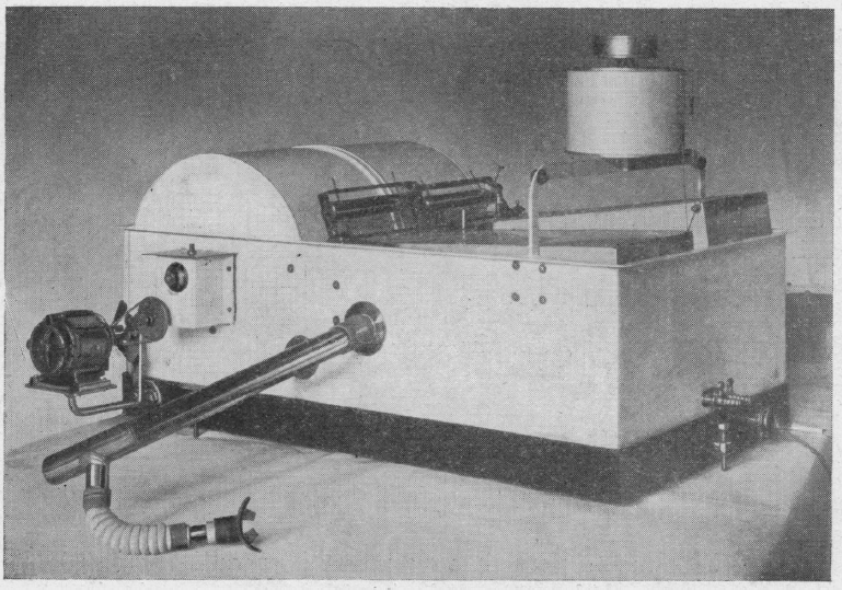
“Figure 2 shows the apparatus in a convenient form which has been in use for about two years with complete satisfaction. The gas meters and spirometers are arranged in a common water-bath, the spirometers recording on a common drum, most conveniently with ink of different colours. The water-bath is fitted with an overflow tube to secure constant water level; it contains about 100 kg. water, and the expired air is led through a pipe of considerable length which is immersed in the bath to cool the air to the temperature of the bath before it enters the gas meter. From the service pipe to the spirometer (B) there is a wide pipe to secure that every change in air pressure caused by the respiration is taken up promptly by the spirometer (B), so that there can be an absolutely constant in the gas meter I.
“The accuracy of the results largely depends on the care with which the spirometers are balanced; every change in the air pressure in one of the spirometers will affect the water level in the corresponding gas meter and so disturb its accuracy. The spirometers are therefore arranged on special bearings and balanced with a double set of counterbalances, a large one for gross and a small one for fine adjustment. The counterbalances are adjustable horizontally and vertically, thus allowing convenient compensation for buoyancy of the spirometer.”